CPU Usage LEDs
This project has now become the AVR USB RGB LED Controller project. The CPU Usage LEDs host program can be found in the examples directory.
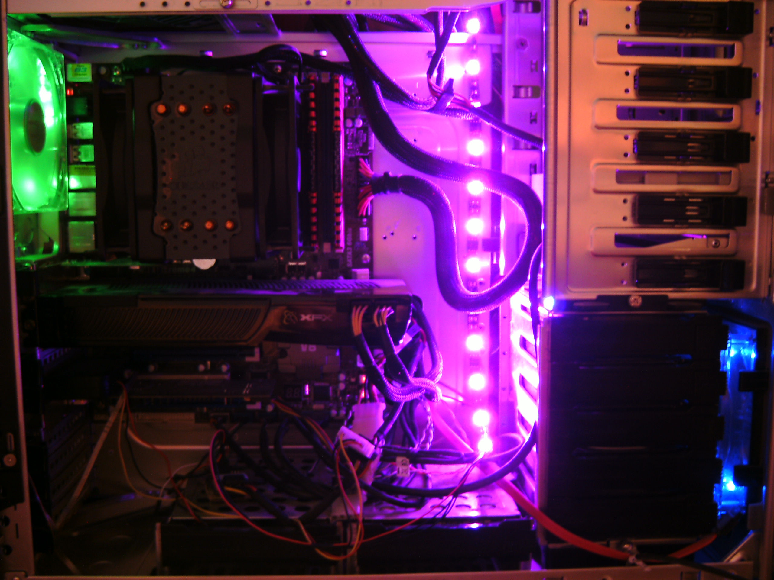
Having seen a few circuits around the web that light up LEDs depending on CPU load I decided to make my own since they do look pretty cool 😀 I was originally going to have it communicate with the PC using a USB to TTL serial converter, but then I found out about the V-USB library which eliminated the need for a converter and supports ATtiny25/45/85 without the need for a crystal, great!
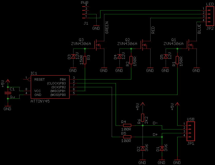
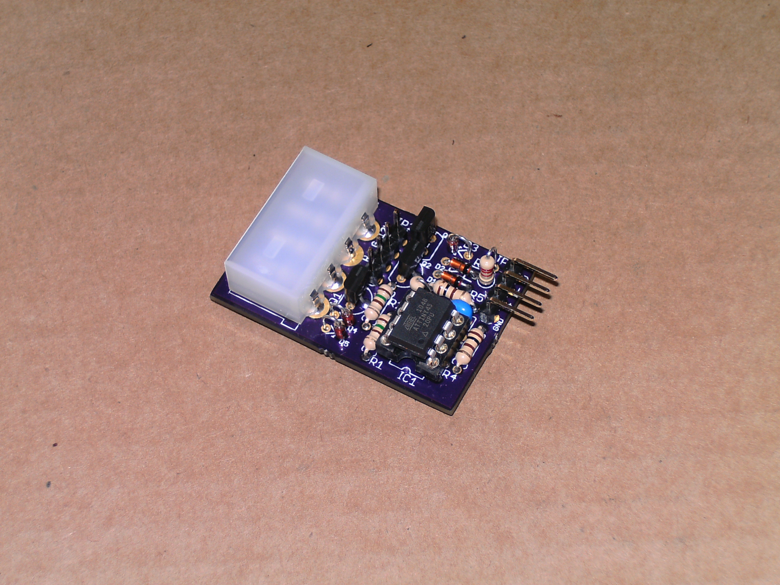
The ATtiny45 has just enough flash and IO pins for the project, with just the reset pin left (2x for power, 2x for USB, 3x for the RGB LEDs). I obtained a 12V 15 LED RGB strip from Ebay for £5.45 and used ZVN4306A MOSFETs to control them, common transistors like 2N4401 or 2N3904 could have been used instead since each colour only draws around 90mA, but the MOSFETs are more efficient with less heat dissipation and allowing a little bit more current to flow.
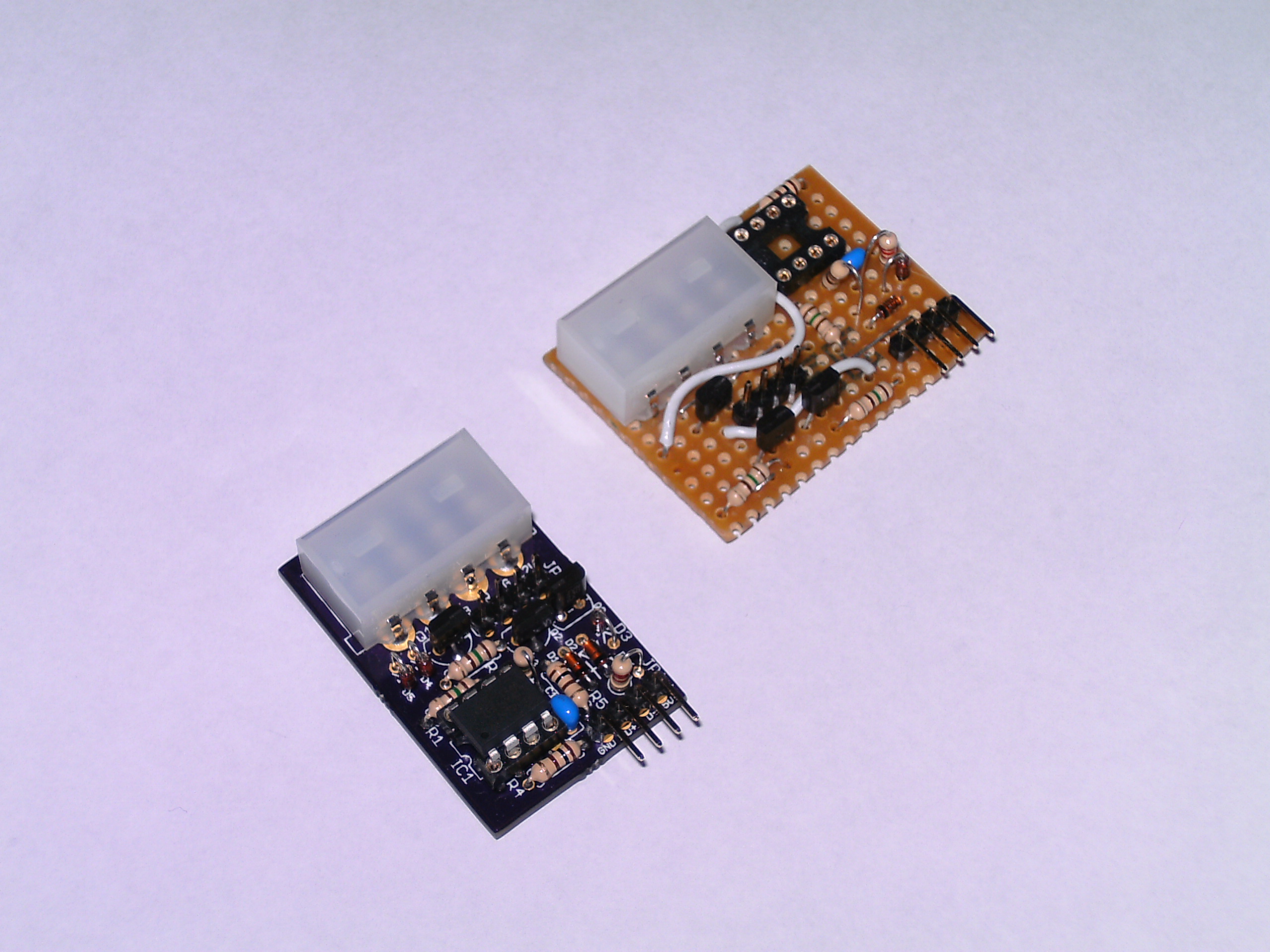
The circuit was first made on strip board without the 12V zener diodes shown in the schematic, but one of the MOSFETs soon stopped working and was stuck on, I presume the gate was fried by static, this prompted for the addition of zener diodes at the MOSFET gates for the PCB version.
Firmware
On to the uC firmware, timers 0 and 1 are used for PWM control of the LEDs running at 500Hz, timer0 is also used for keeping an approximate track of milliseconds which is used for idle timeout, EEPROM 4 second save delay to help increase EEPROM life and LED colour transition time, with the idle timeout when it doesn’t receive any data for 5 seconds it will start to transition through blue, green, red and back until it starts getting USB data again.
As well as being able to change colour based on CPU usage it can also be set to a single static colour, perhaps it’s a little dark in your PC case, you can set it to white :D. The settings are saved to the EEPROM so next time the PC is booted it will go back to the colour it had previously been set to.
Alternative components
If you use normal transistors instead of MOSFETs, R1, R2 and R3 should be changed to around 1K – 2.2K and the zener diodes D3, D4 and D5 can be removed. D3, D4 and D5 can also be removed if you use MOSFETs with internal zener diodes or if you just don’t want/need ESD protection. C1 filter capacitor can be any value from 100nF to 1uF and preferably ceramic.
Host program
The host program is written in C and available for Windows and Linux, though the Linux program is a bit limited in features at the moment, only the main function of sending the current CPU load has been implemented.
Downloads
Latest downloads can be found HERE.


Comments