PWM Fan controllers using the 555 timer IC
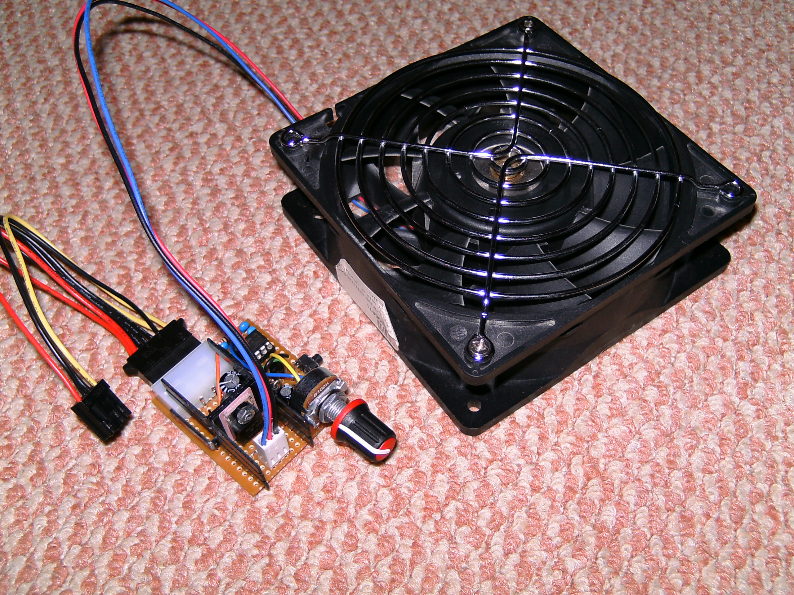
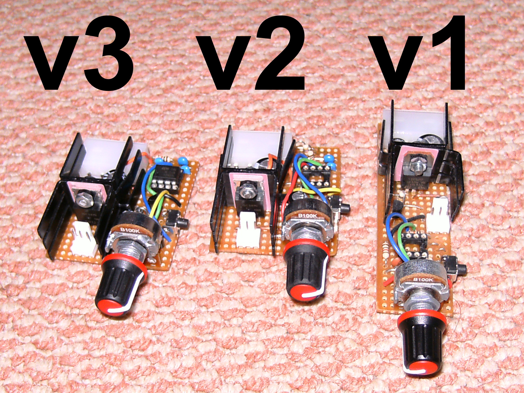
Here I made 3 slightly different PWM fan controllers based on the 555 timer for controlling a large server fan – Delta FFB1212EHE, 3A peak, 2A normal load, other features of these controllers are to boost the fan on to 100% for the first few seconds of receiving power and a ‘turbo’ button to set fan speed to 100% while pressed.
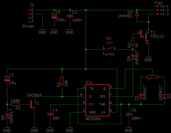
Version 1 (July 2010) of the controller the turn on boost didn’t quite work as expected, rather than stay at 100% for the first few seconds it instead stayed at 0%, enough though in falstad circuit sim it would go to 100%, another problem was that it would occasionally slow down to almost stopping and I’d have to reset it to get it back to normal, I’ve no idea what caused this but it doesn’t seem to effect the later versions.

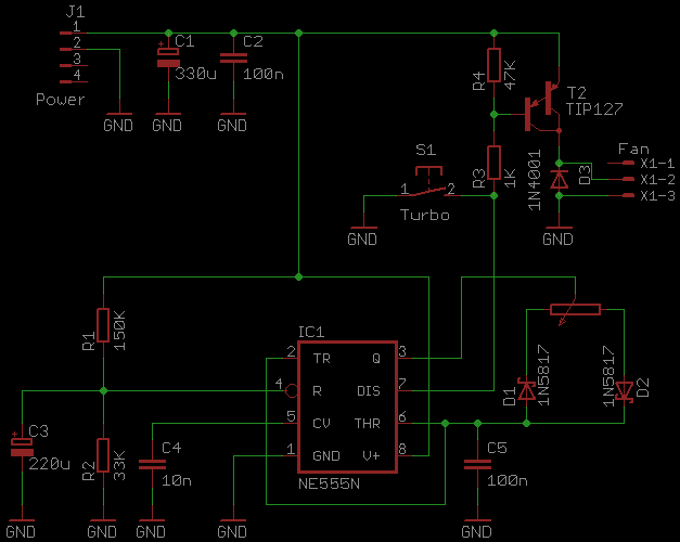
Version 2 (January 2011) fixed the turn on boost problem by using a PNP output transistor, I changed the turn on boost timer to reduce component count but now the timer capacitor has a slow discharge time and because of this, turning the controller off and back on too quickly would bypass the turn on boost as the capacitor voltage would still above the 555 reset voltage threshold (~0.7V).

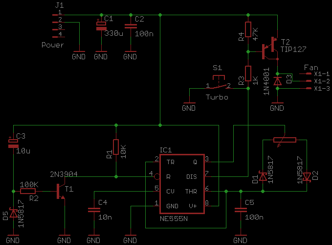
Version 3 (February 2011) is the same as the version 1, but with a PNP output transistor instead of an NPN like version 2, this inverted the on/off operation so when version 1 was normally off version 3 is on.
In the schematics below, D3 (which is connected anti-parallel to the fan) is probably not needed for normal PC brushless fans since they contain a bunch of circuitry between the power and coils that deals with the flyback spikes. R4 in v2 and v3 (47K pull up resistor) may not be needed if the transistor contains internal resistors between the emitter and base.
Updates – July 2012
In these circuits I used darlington transistors as the switching devices, TIP122 in the first controller and TIP127 in the last two controllers, with a 2A load and 0.9Vce they dissipate 1.8W of heat (2A * 0.9Vce = 1.8W) (even more if switching losses are calculated) which requires some form of heatsink, I could have used smaller heatsinks or even MOSFETs and use no heatsink at all ((0.1R * (2A ^ 2)) = 400mW), but these were made in a time before I used MOSFETs or knew how to workout how much heat would be dissipated. Also using prototyping board would have been a good idea here. 🙂
Fan controllers using AVR microcontrollers and MOSFETs

Comments