Raspberry Pi 4 PCI-Express Bridge “Chip”
After seeing the work done by Thomasz Mloduchowski and Colin Riley with managing to bridge the Raspberry Pi 4’s PCI-Express bus to a USB 3.0 port, and then seeing these comments on hack-a-day, I thought I would give it a go too!
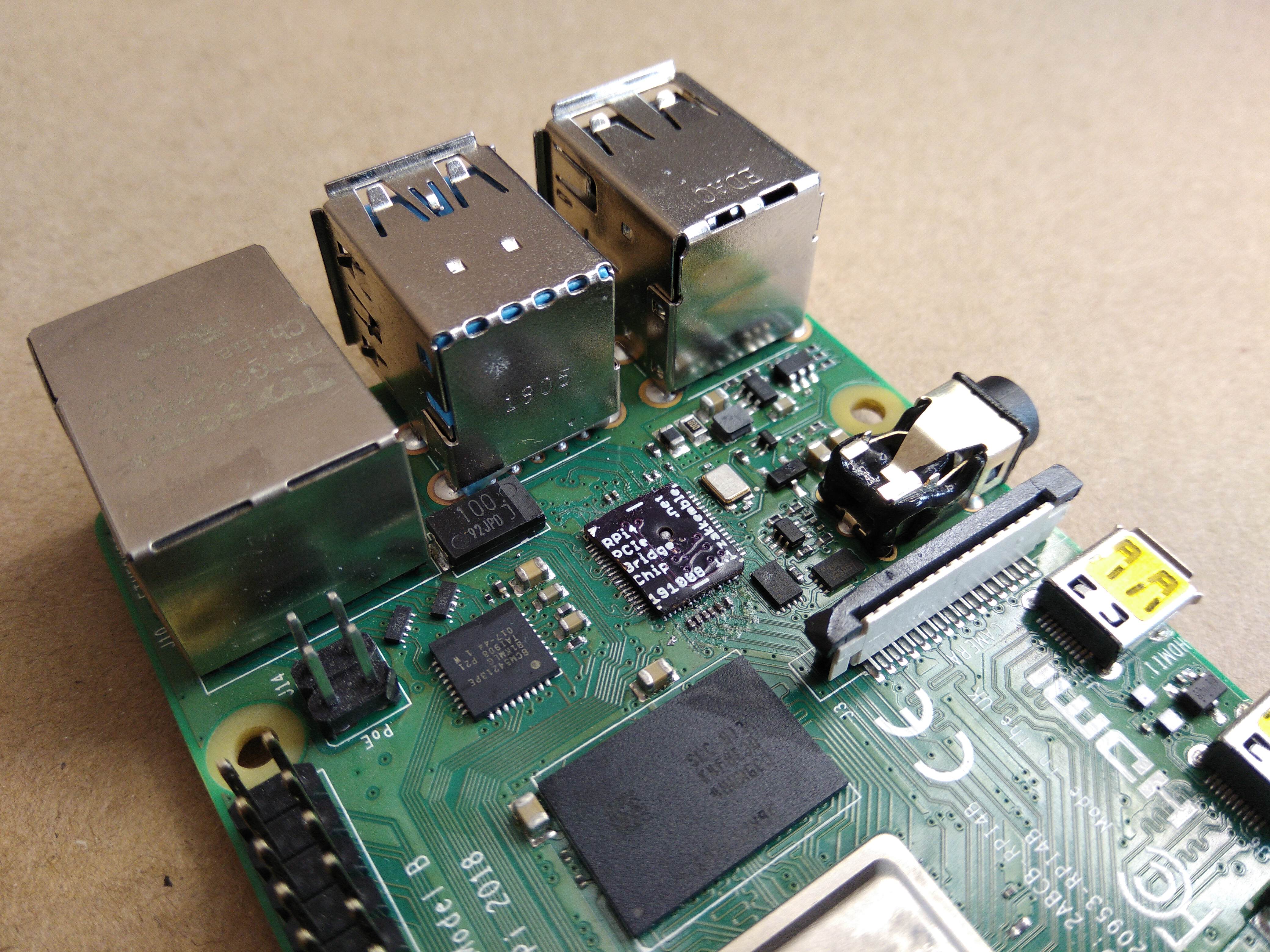
So, here’s a PCIe bridge “chip” that simply replaces the VL805 USB 3.0 controller chip on the Pi, giving access to the PCI-Express bus on a USB 3.0 port. However, this does mean losing all USB functionality of the Pi. That could be a bit of a problem if you ever mess up the networking and need to attach a keyboard. Never mind, it seems that the USB-C power connector can run as a USB host, allowing a keyboard to be connected if 5V power is supplied through the GPIO header instead.
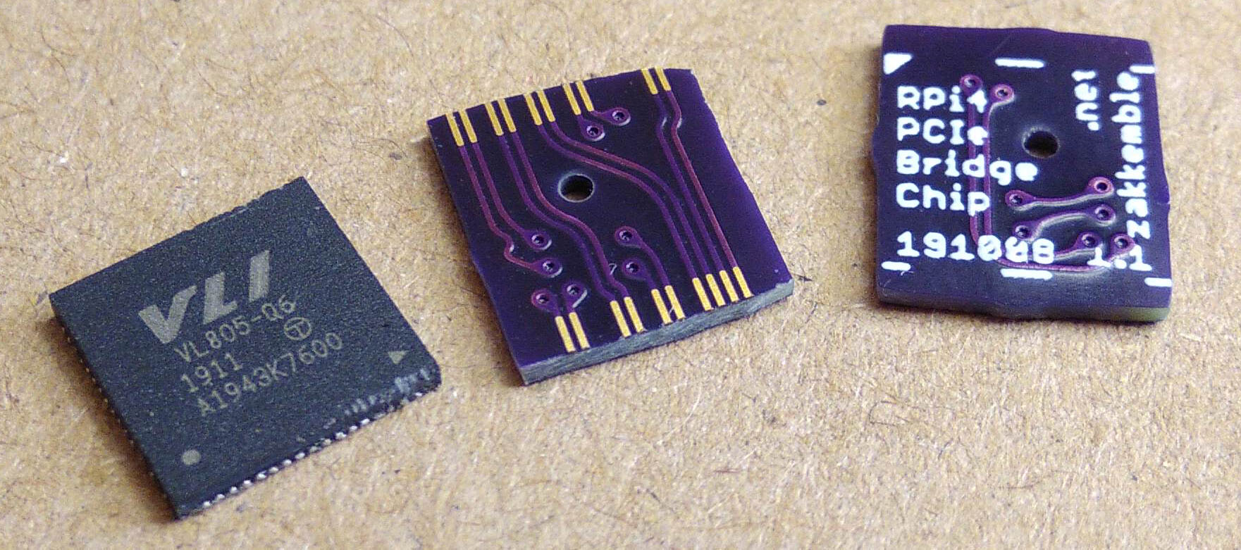
The bridge “chip” is a 0.8mm thick PCB from OSHPark with copper pads in the same locations as a real VL805 QFN68 IC package, then traces connecting the PCIe pads to the USB pads that connect to the upper USB 3.0 port. RESET, WAKE and a few other signals were also connected to the lower USB 3.0 port.
| PCIe Signal | Direction | USB Signal |
|---|---|---|
| REFCLK+ | Host -> Device | D- |
| REFCLK- | Host -> Device | D+ |
| HSO+ | Host (TX) -> Device (RX) | RX- |
| HSO- | Host (TX) -> Device (RX) | RX+ |
| HSI+ | Device (TX) -> Host (RX) | TX- |
| HSI- | Device (TX) -> Host (RX) | TX+ |
| RESET | Host -> Device | D- (lower port) |
| WAKE (not connected anywhere) | Device -> Host | D+ (lower port) |
| CLKREQ | Host -> Device | RX+ (lower port) |
| PONRST | Not a PCIe signal, connected like a reset pin on a microcontroller. |
RX- (lower port) |
HSI and HSO (in and out) are from the perspective of the host controller. Where host HSO/TX will connect to device RX and host HSI/RX to device TX. Man, this is really confusing with TX, RX, device, host, passing through USB, which side is which... 😕
There’s also a small hole near the centre, this allows any leftover solder from the large ground pad to have somewhere to go when placing the chip, otherwise the solder could end up squashed out around the edge, shorting out the pads. The PCB is slightly larger than the QFN68 package, as there is a limit on how close the copper can be to the edge. The fabricated PCB should be sanded down to the correct size, so that the cross-section of the copper pads can be seen at the edge of the PCB, just like on a QFN package.

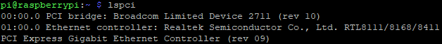
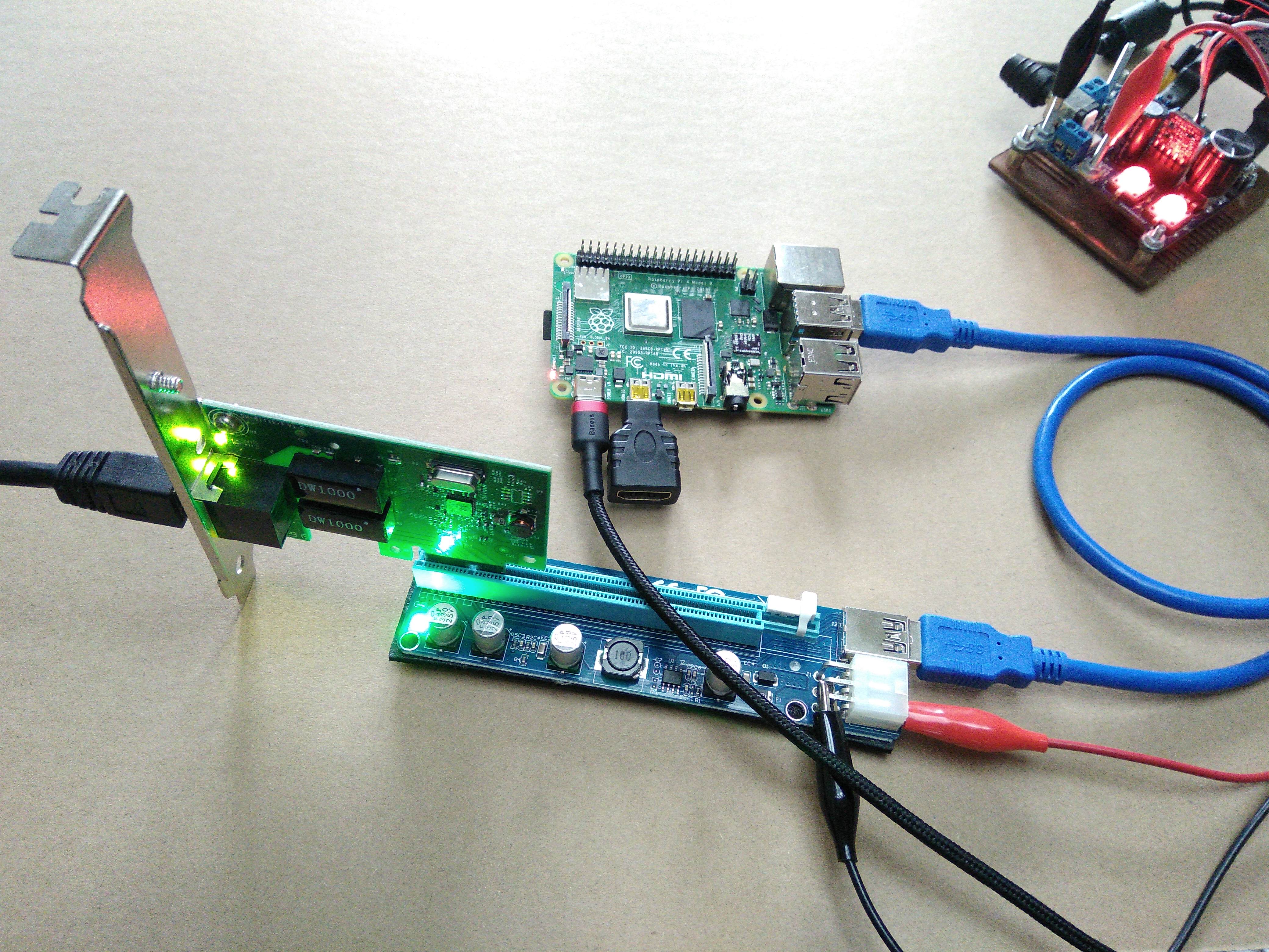
After replacing the VL805 with the bridge chip I tried a few PCIe cards that were laying around, the first was a Realtek RTL8168 based ethernet adapter… it didn’t work. Then I tried an ASMedia ASM1083 PCIe to PCI converter, that didn’t work either. I looked over all solder joints, checked for continuity, shorts, and everything seemed fine. I tried all kinds of things, like removing the capacitors and swapping the + and – of each signal in case they were swapped at the device end, as this is a feature of PCIe called polarity inversion that maybe the controller did not support. The Pi just would not detect them. It seemed to be unable to train the PCIe link as dmesg showed link down instead of link up, 2.5 Gbps x1 (!SSC). In the end I ordered a USB 3.0 expansion card containing a VL805, the same as the Pi. When it eventually arrived, I plugged it in and it was detected first time! I found a Realtek RTL8111 based ethernet adapter, and that worked too! After installing the driver for the RTL8111 it was able to obtain an IP from the DHCP server and I could ping the interface.
I wonder what it is about the RTL8168 and ASM1083 that makes them incompatible with the Raspberry Pi? Maybe they just don’t like the PCIe signals running through a load of USB connectors and cables.
UPDATE 1: Using an ASM1184e PCIe switch and these two expansion cards are still not detected, so probably not signal issues. The device trees file has been modified to allow more than one PCIe device, as described in Colins blog post. Other cards work in the switch, just not these two.
UDPATE 2: Nevermind, the problem with the ASM1083 was that I hadn’t connected the 5V rail, and is now detected by the Pi. RTL8168 still doesn’t work for some reason.
A quick test using 4 USB 3.0 flash drives plugged into the VL805 expansion card resulted with a total read throughput of 3 Gbps out of a maximum theoretical throughput of 4 Gbps over a 5 Gbps PCIe 2.0 link. The flash drives had their read speeds almost maxed out, probably slowed down slightly from overhead of having to switch between each drive while reading.
UPDATE: Another test with 5 USB flash drives, a USB hub and a USB-to-Ethernet adapter resulted in 3 Gbps again, so this seems like a limitation of the VL805 or CPU. Other RPi4 benchmarks using SSDs through USB 3 also maxed out at 3 Gbps.
The RESET and WAKE traces on the riser board should be cut, otherwise RESET will be connected to GND preventing the card from starting and WAKE will be connected to 5V possibly damaging the device if that pin is not 5V tolerant. The RESET line should then have a 10k pullup connected to the 3.3V supply, or connected to the D- signal of the lower USB 3.0 port of the Pi.
Colin mentioned that Thomasz also had kernel panic problems with his setup, I had a few panics and freezes too, but they seemed to be caused by wiggling the PCIe card a little too much.
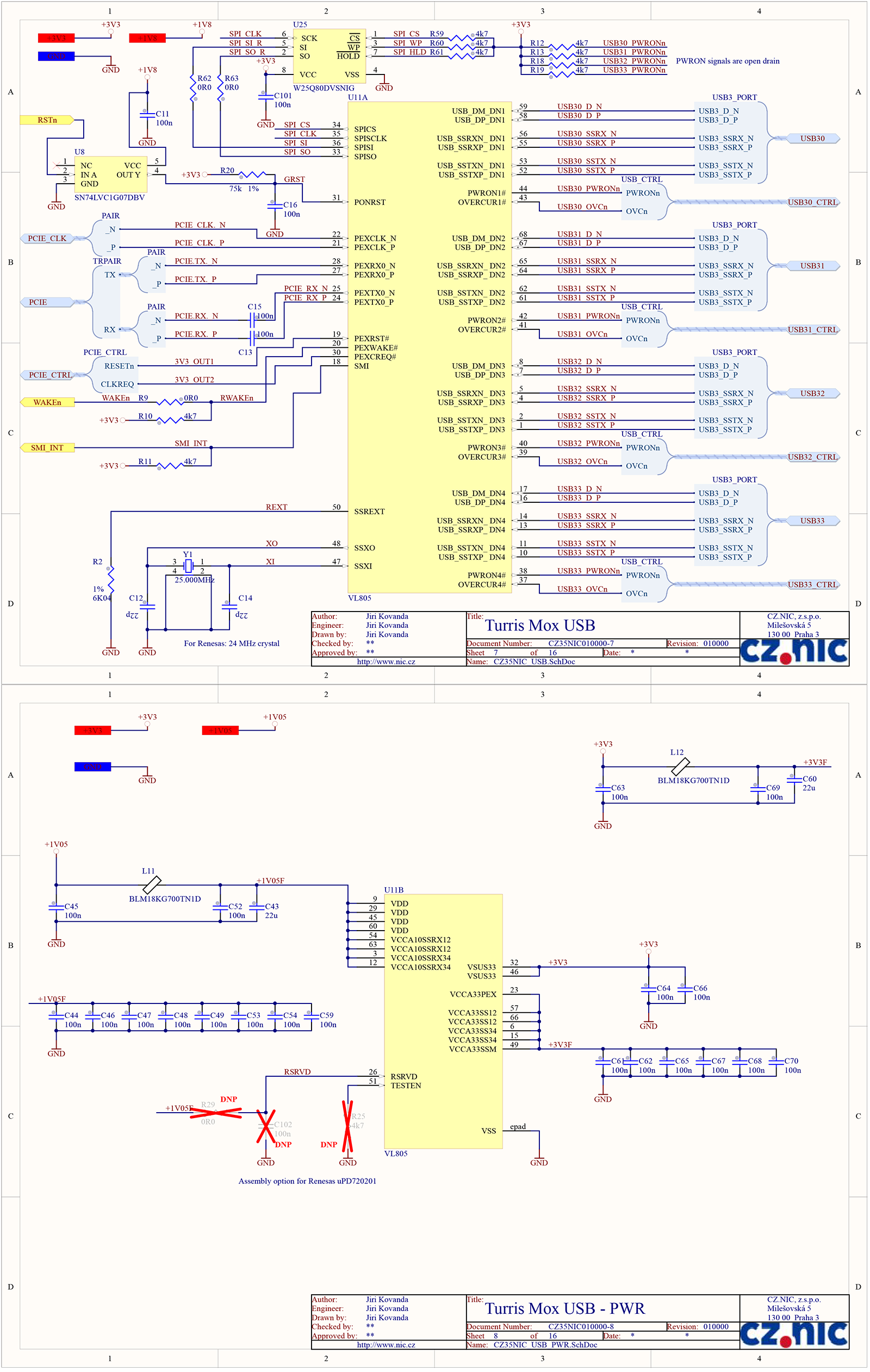
This pdf has a full schematic using a VL805 on pages 7 and 8 (pictured below), very handy since any information about the chip is scarce.
PCB designs and things are on GitHub

Comments