Laptop Bench Power Supply
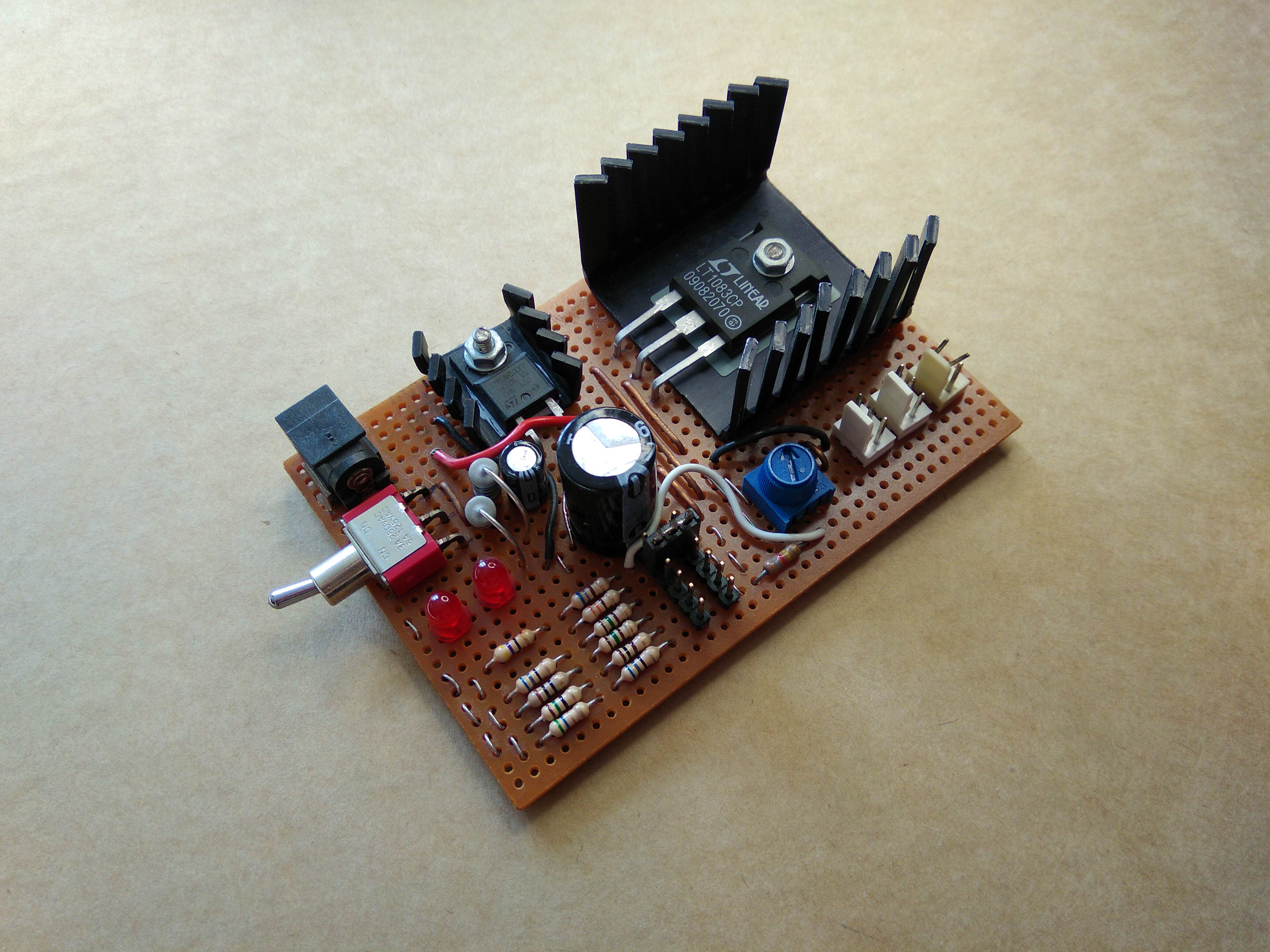
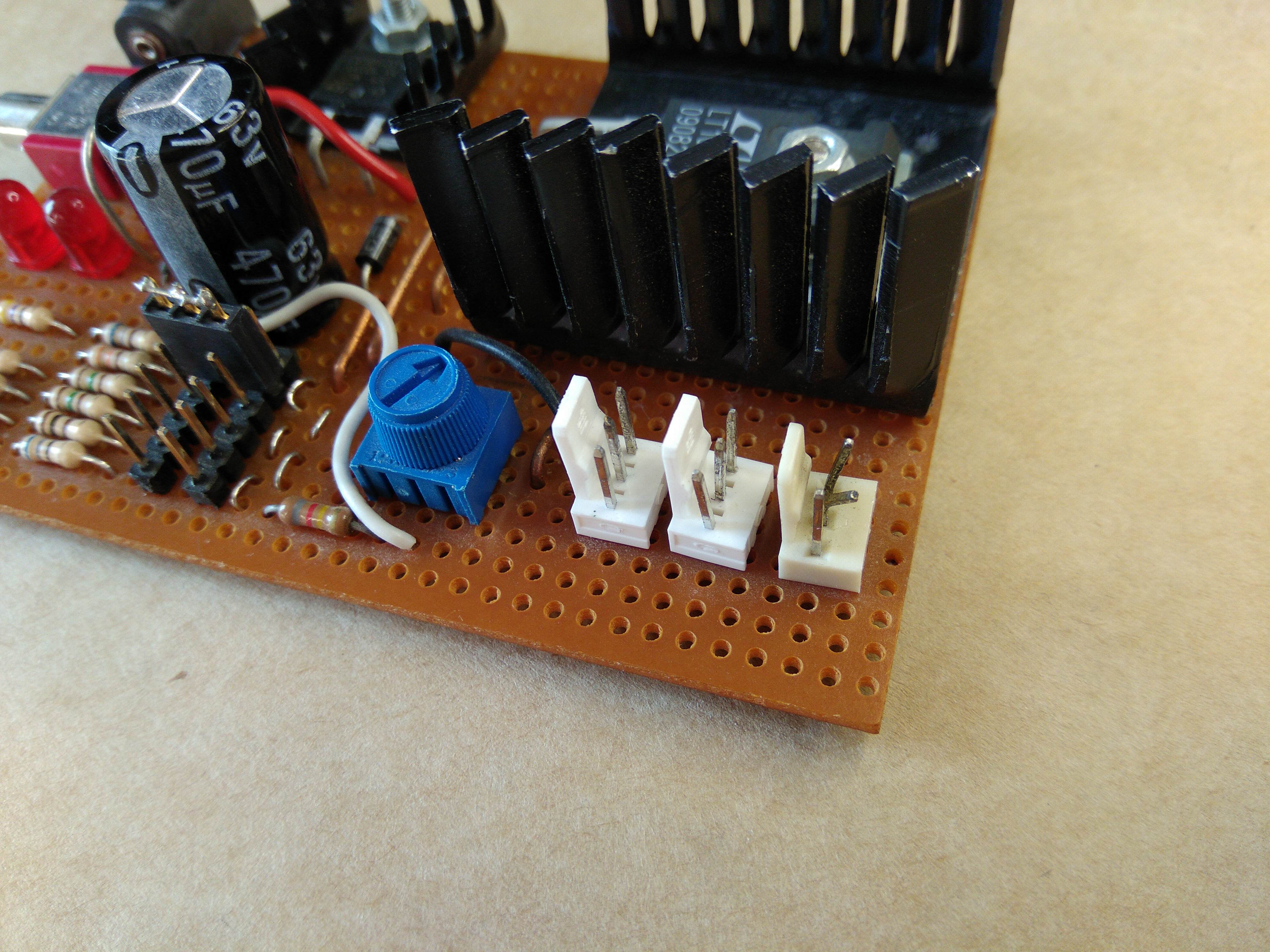
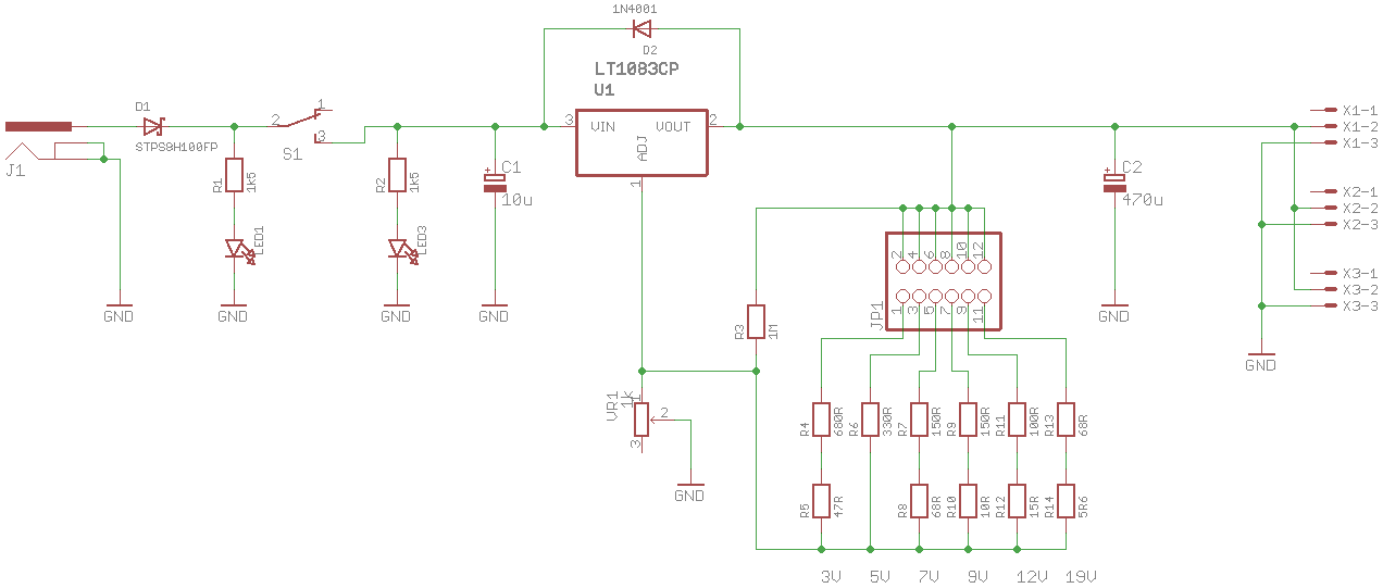
Many years ago (September 2009) I made a simple bench power supply using an LT1083 7.5A linear regulator with adjustable output voltage designed to be used with a 19.5V 3.42A laptop power supply. It still works fine after years of abuse, but my choice of output power connectors was poor (3 pin headers, the sort used for PC fans), it’s made on strip board and cooling was sometimes a problem, so time for an upgrade!
Real bench power supplies usually have features like adjustable current limiting and displays showing voltage and current. I continued to keep things simple (kind of) so none of that stuff was added, I also didn’t want to spend too much time on this project. Displays and current limiters can be easily added later anyway, going between the output of the power supply and the load.
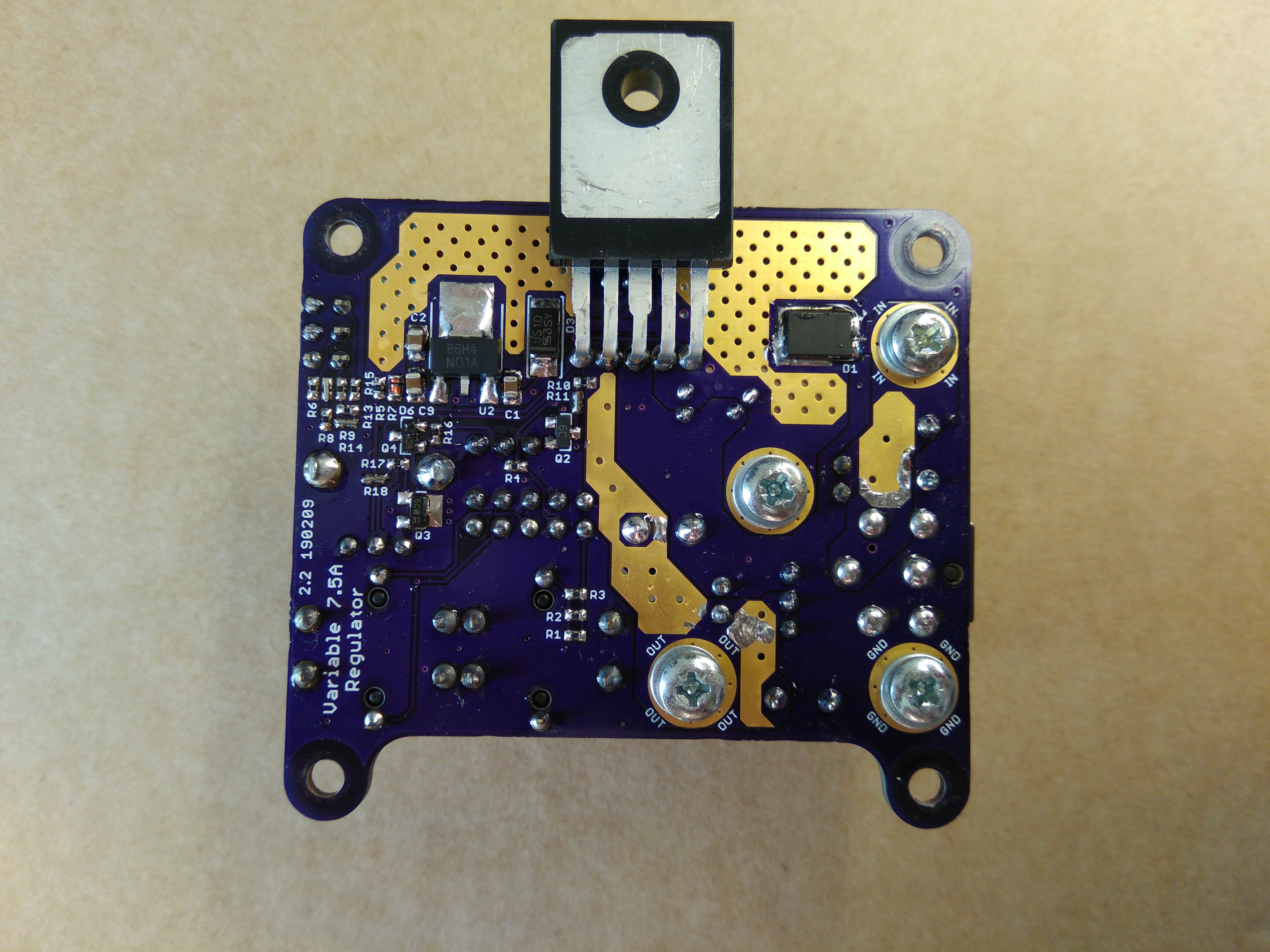
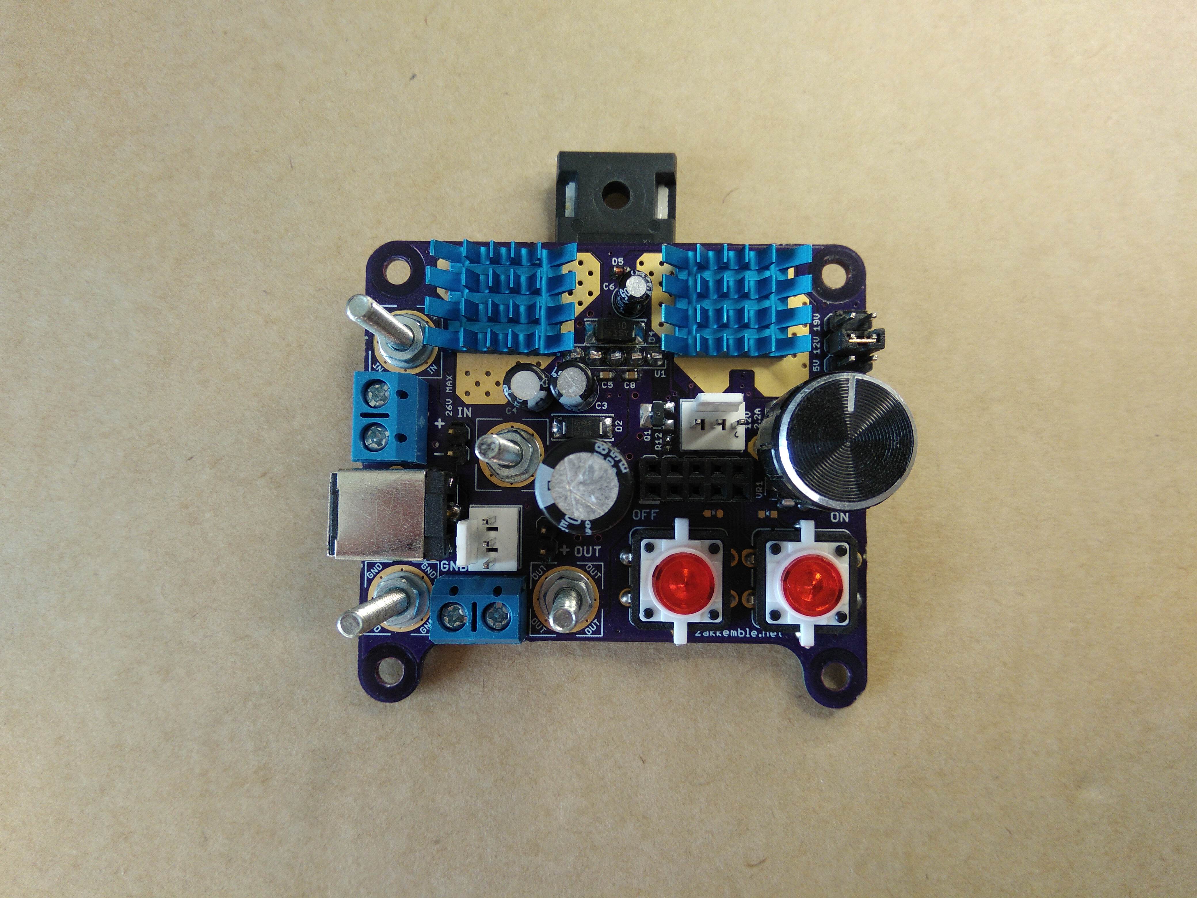
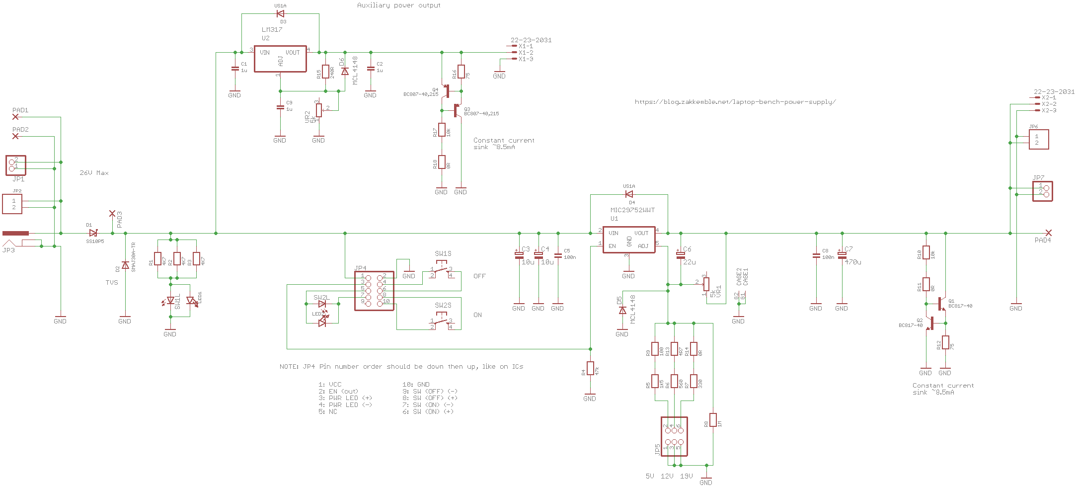
LT1083 regulator ICs are no longer manufactured. They’re still available from China, but are most likely fakes. I found that the MIC29752 is very similar, with a few extra features like an enable pin allowing for easier power control, which is good since I wanted to remove the original power switch and use some kind of solid-state design. Without the enable pin some MOSFETs would have had to be added.
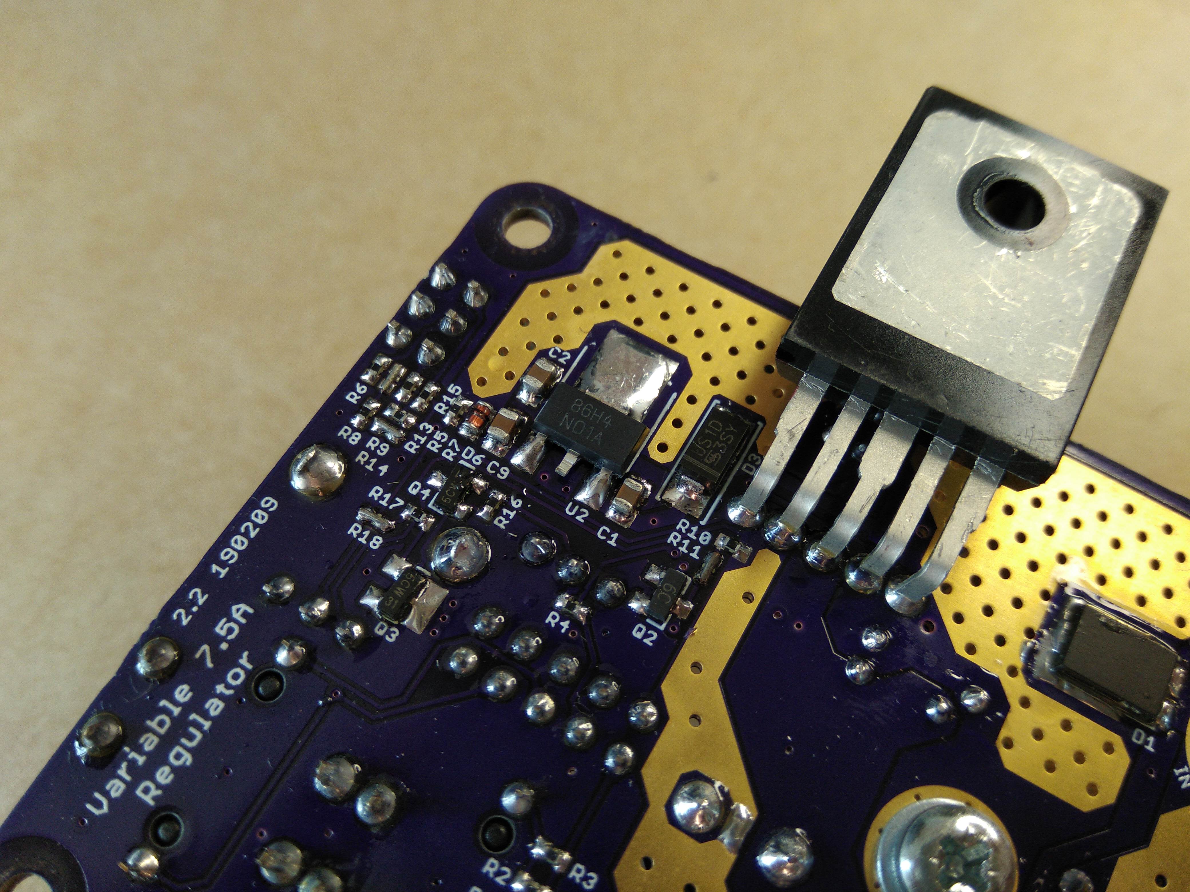
I often needed a second supply voltage so an auxiliary output was added using an LM317 regulator, with adjustable output voltage via a small trim potentiometer. The first PCB revision had the pads wired all wrong (based on an L78M), and upon powering up the board it quickly popped leaving a small hole in it.
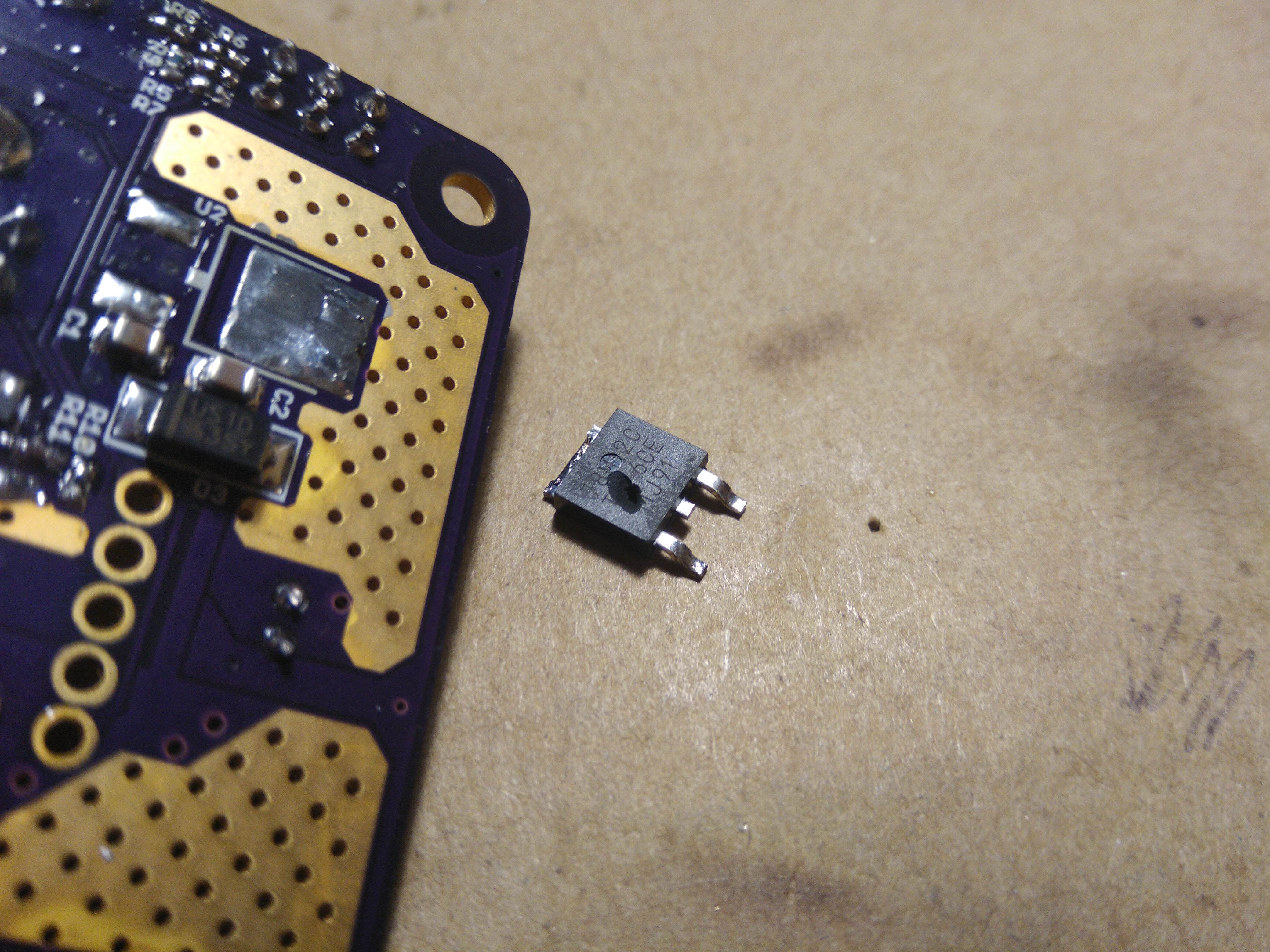
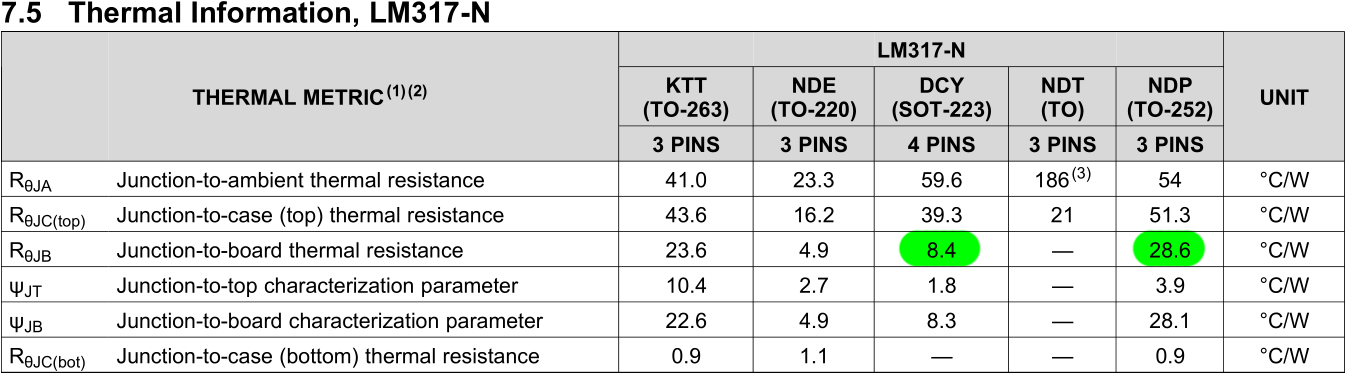
I also noticed that the SOT-223 package of the LM317 had a much lower junction-to-board thermal resistance and higher current limit than the larger SOT-252-3/DPAK package, which seemed unusual, so I brought both types and tried them on the board. I found that the SOT-223 could dissipate far more power than the larger SOT-252 package before it started to thermally limit itself. I thought it would have been the other way around? Not to worry, the SOT-223 package sits nicely into the SOT-252 footprint.
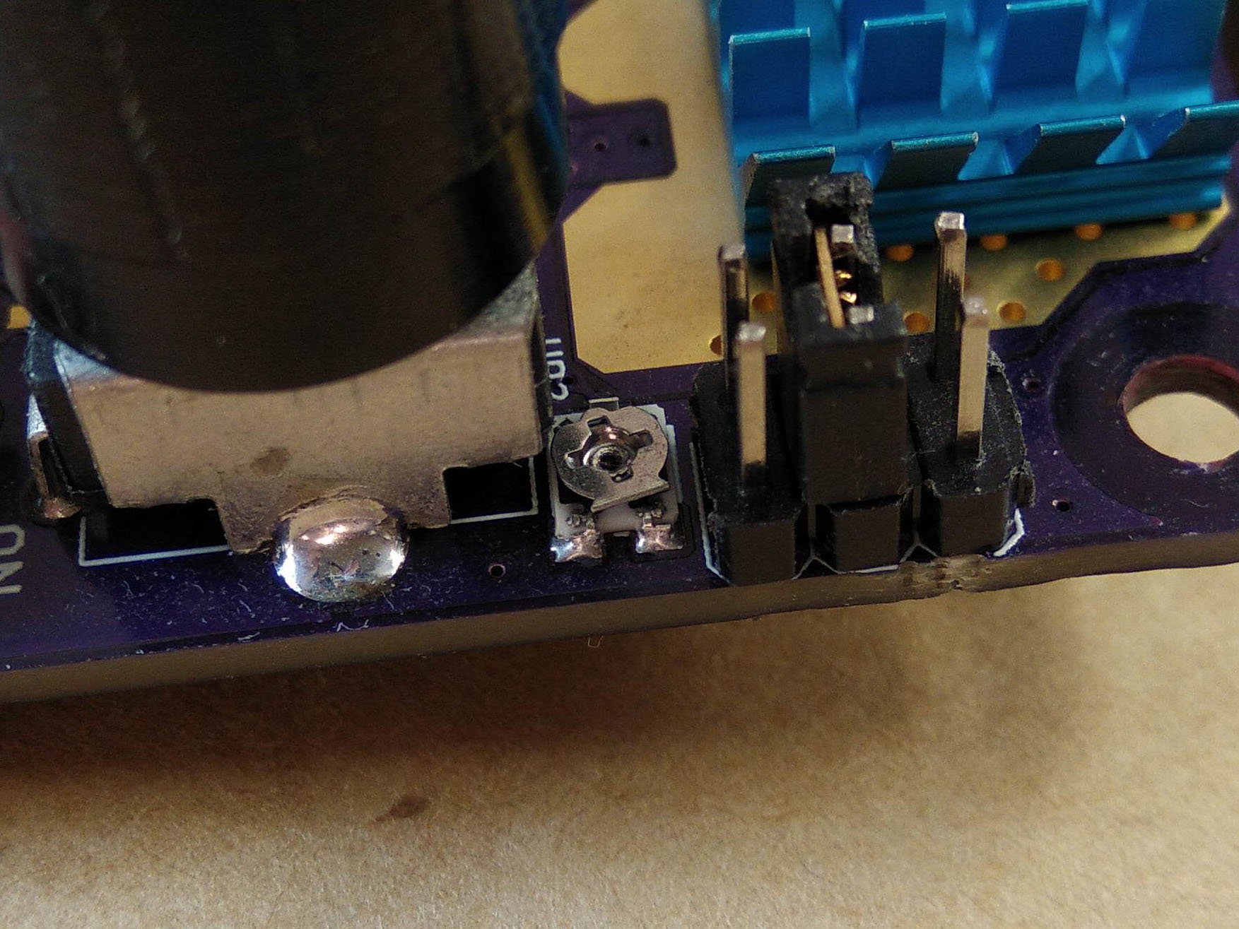
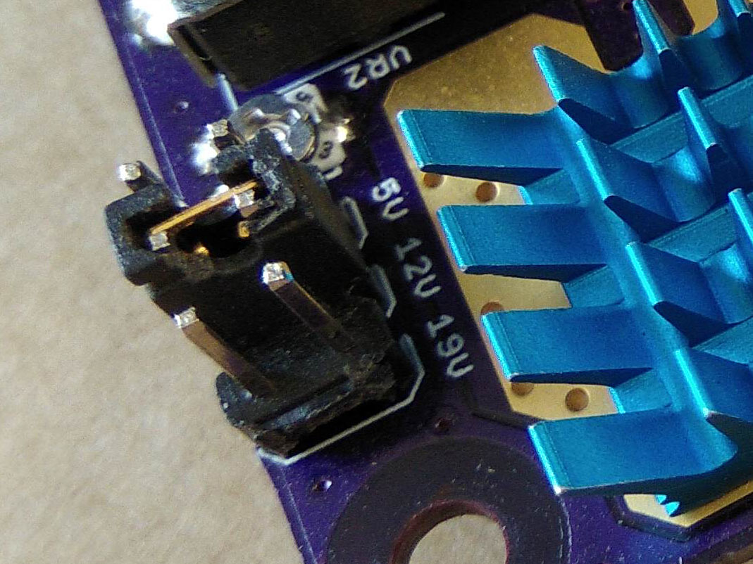
The old power supply also had a selector jumper for 6 voltage ranges; 3V, 5V, 7V, 9V, 12V and 19V. I think I’ve only ever used the 5V, 12V and 19V ranges, so that’s all the new power supply now has. Having a voltage range selector makes fine adjustments to the output voltage easier and also works as a bit of a fail-safe so you don’t accidently turn the voltage control knob all the way to 19V when attached to a 5V circuit!
All of these regulator ICs need to have a minimum load current of 5-10mA to keep the output voltage stable, so a 8.5mA constant current sink was added to each output. The old power supply didn’t have anything to create a minimum current load, but I’ve never noticed any problems. The feedback resistors probably drew enough current to keep things stable.
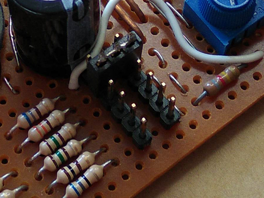
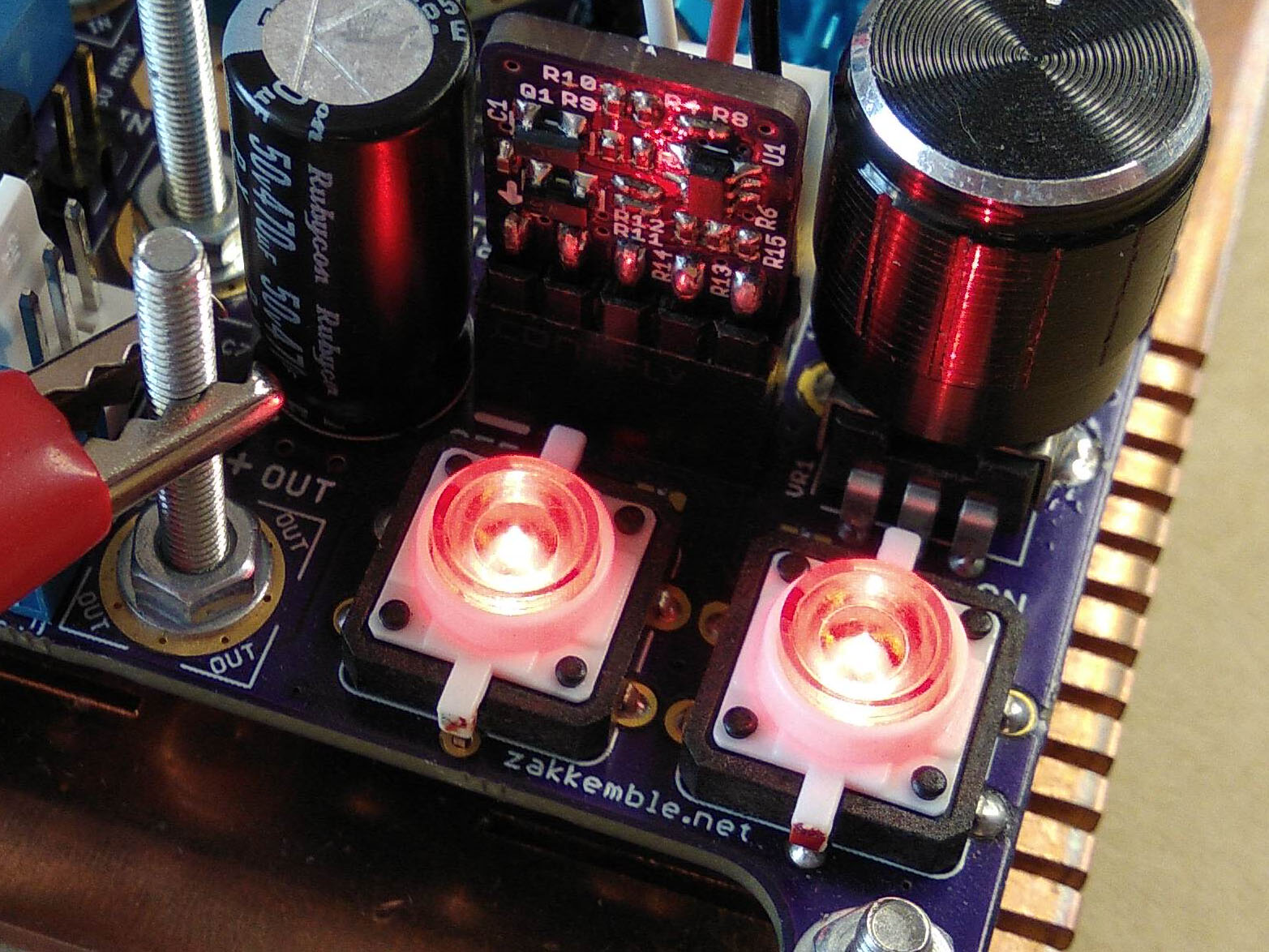
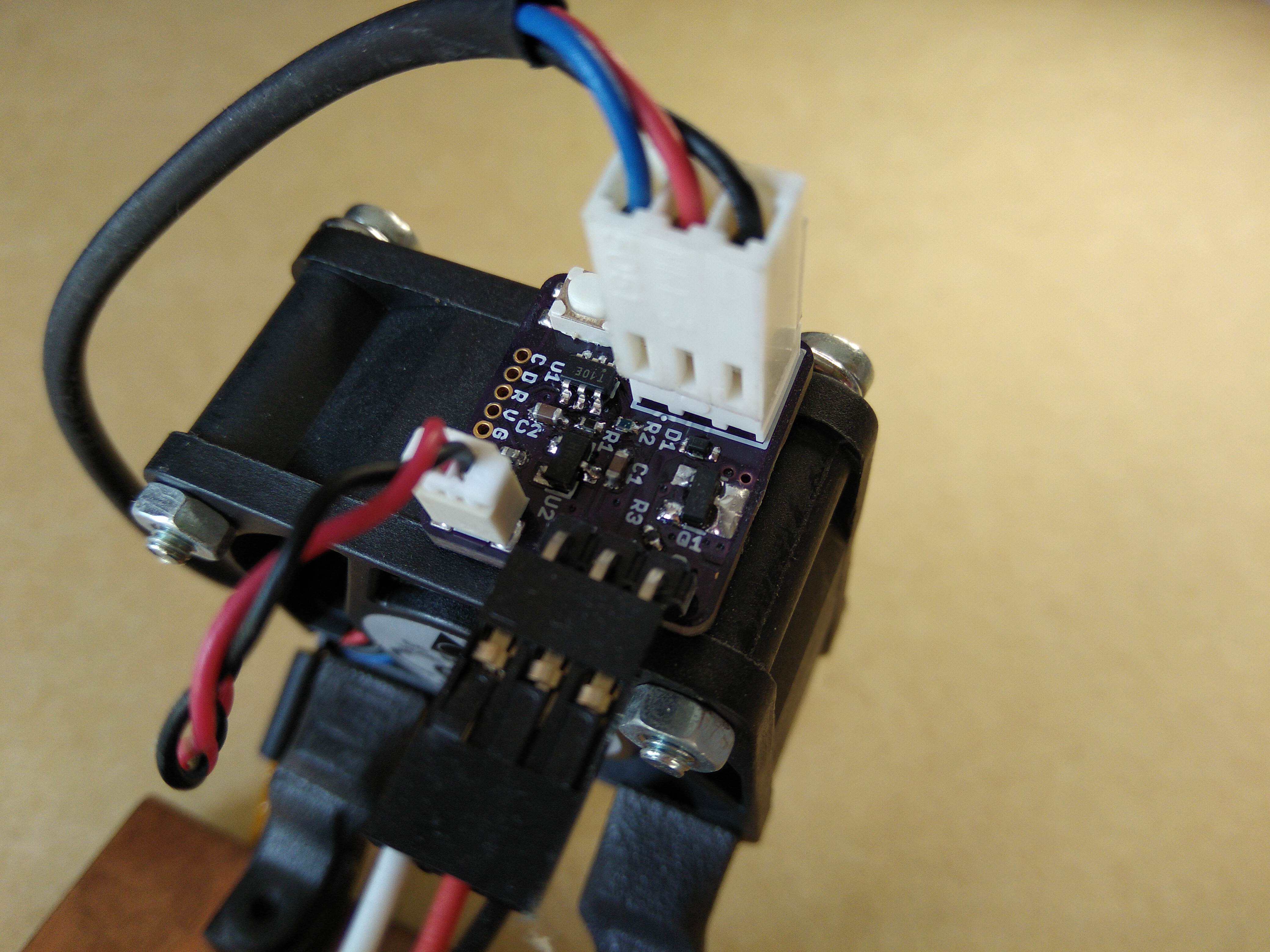
Power is now controlled via 2 push buttons with integrated LEDs, attached to a small, plug-in, all-analogue, control board for debouncing and controlling the enable pin of the main regulator IC. The control board can be swapped out, allowing for changing the behaviour of the buttons and LEDs or even external control of the power supply.
At the moment, the left button turns the power supply off and the right button turns it on. Holding the ‘off’ button turns the ‘on’ button into a momentary-style button, useful for when you want to only briefly apply power for smoke testing.
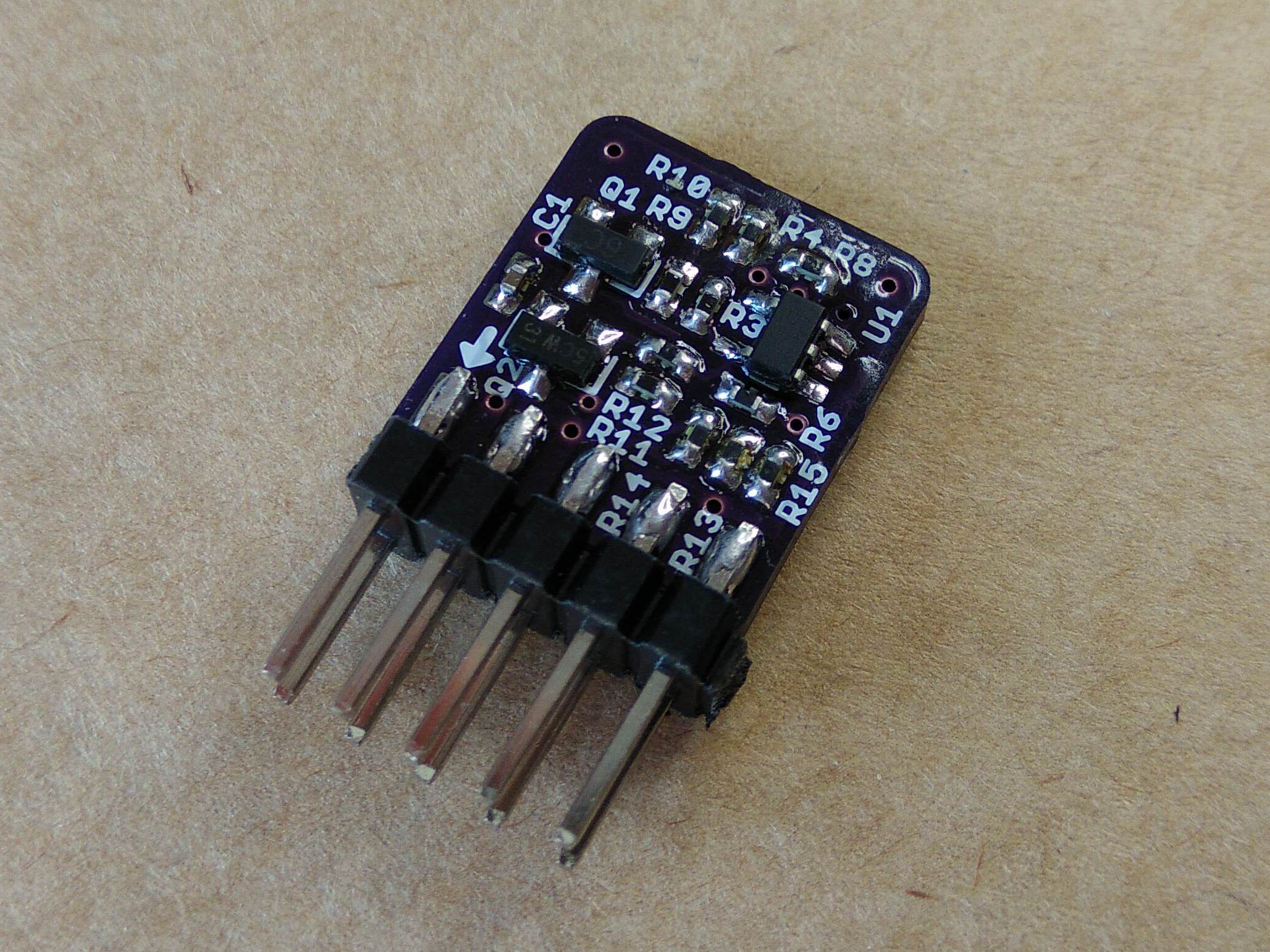
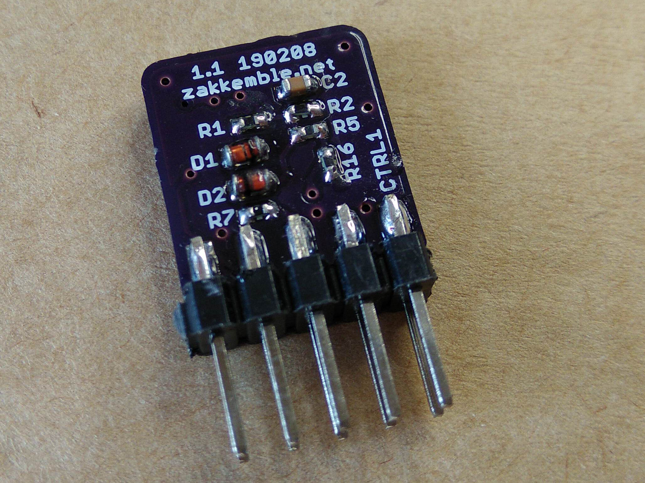
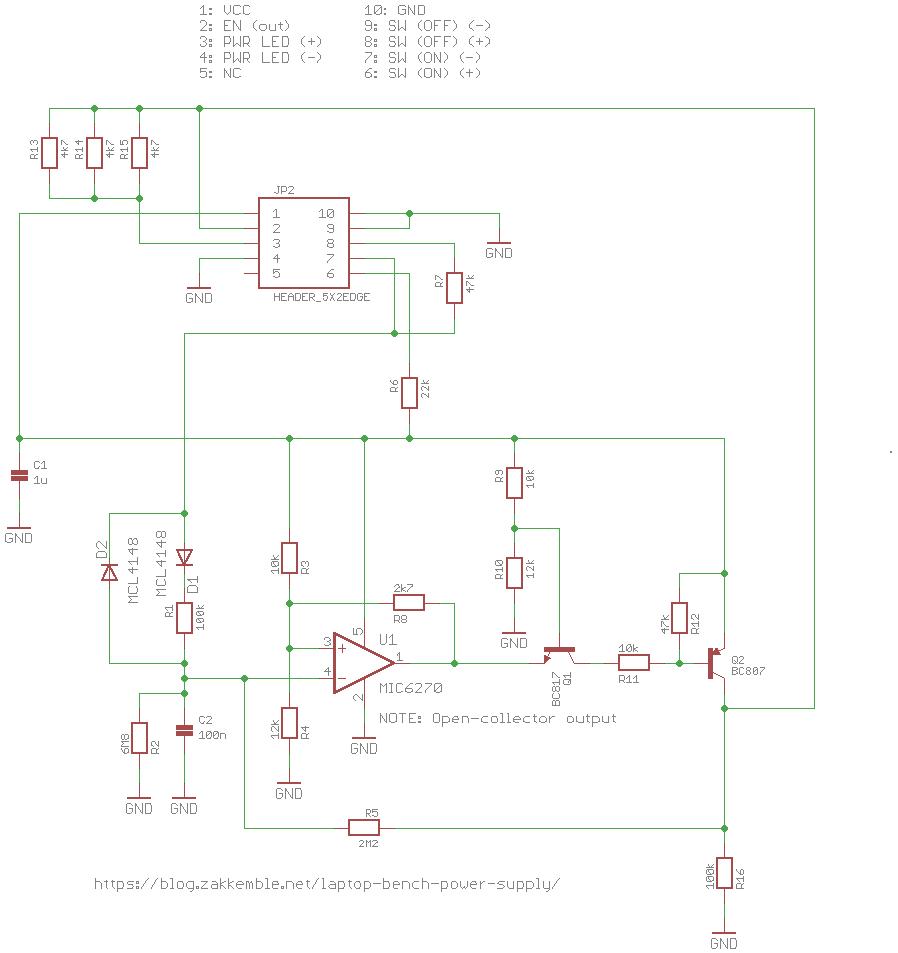
The control circuit has a few more components than most latching comparator circuits, as I wanted it to remember the on/off state for around 250ms after losing power (state is stored in C2) since the laptop PSU cycles on-off-on-off during overload and I didn’t want the regulator to reset back to off when this happened. It also needed to be able to handle debouncing when both buttons are pressed at the same time when creating the momentary-style ‘on’ button. Q2 inverts the comparator output and Q1 is needed otherwise Q2 will never turn off as current can pass through R8 and R4 to ground. Simulate the circuit on [Falstad Circuit Sim].
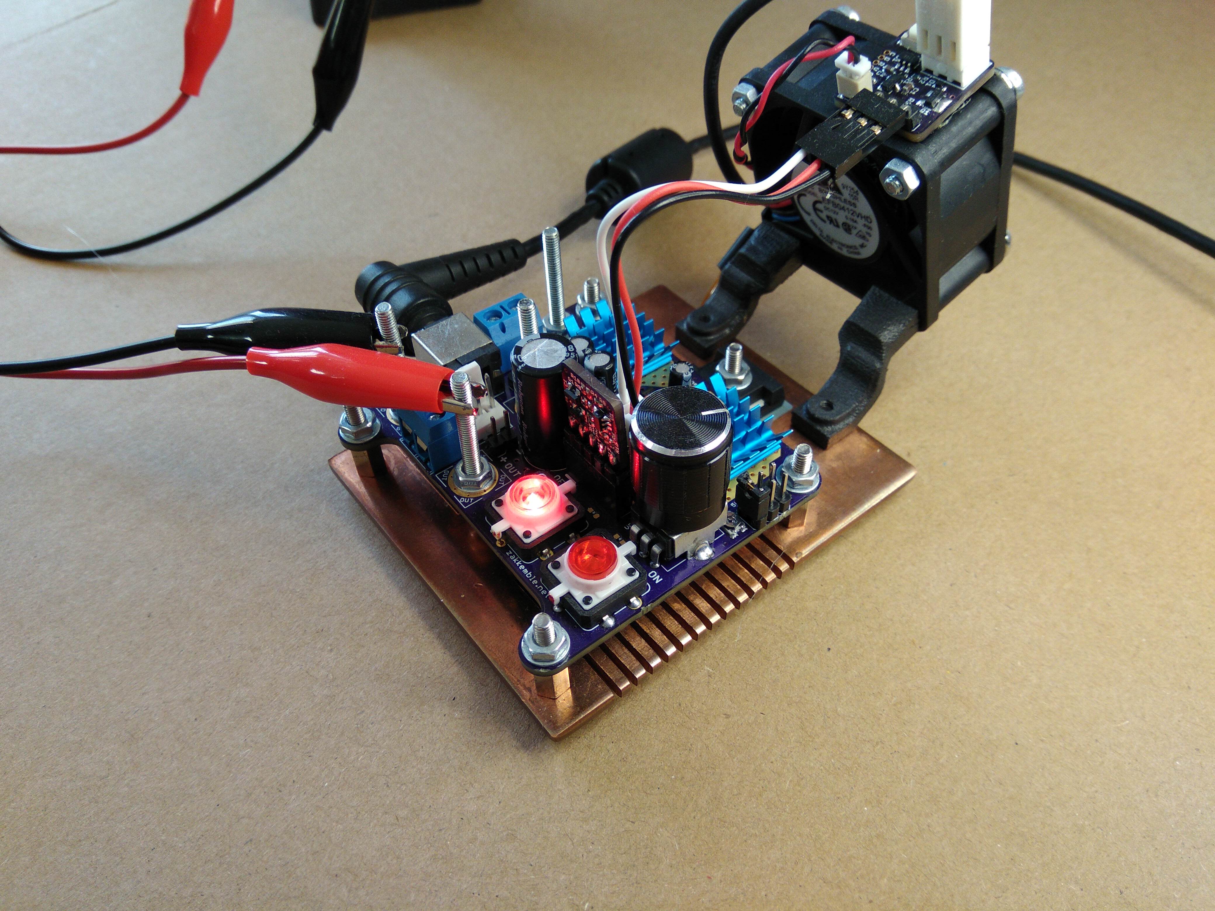
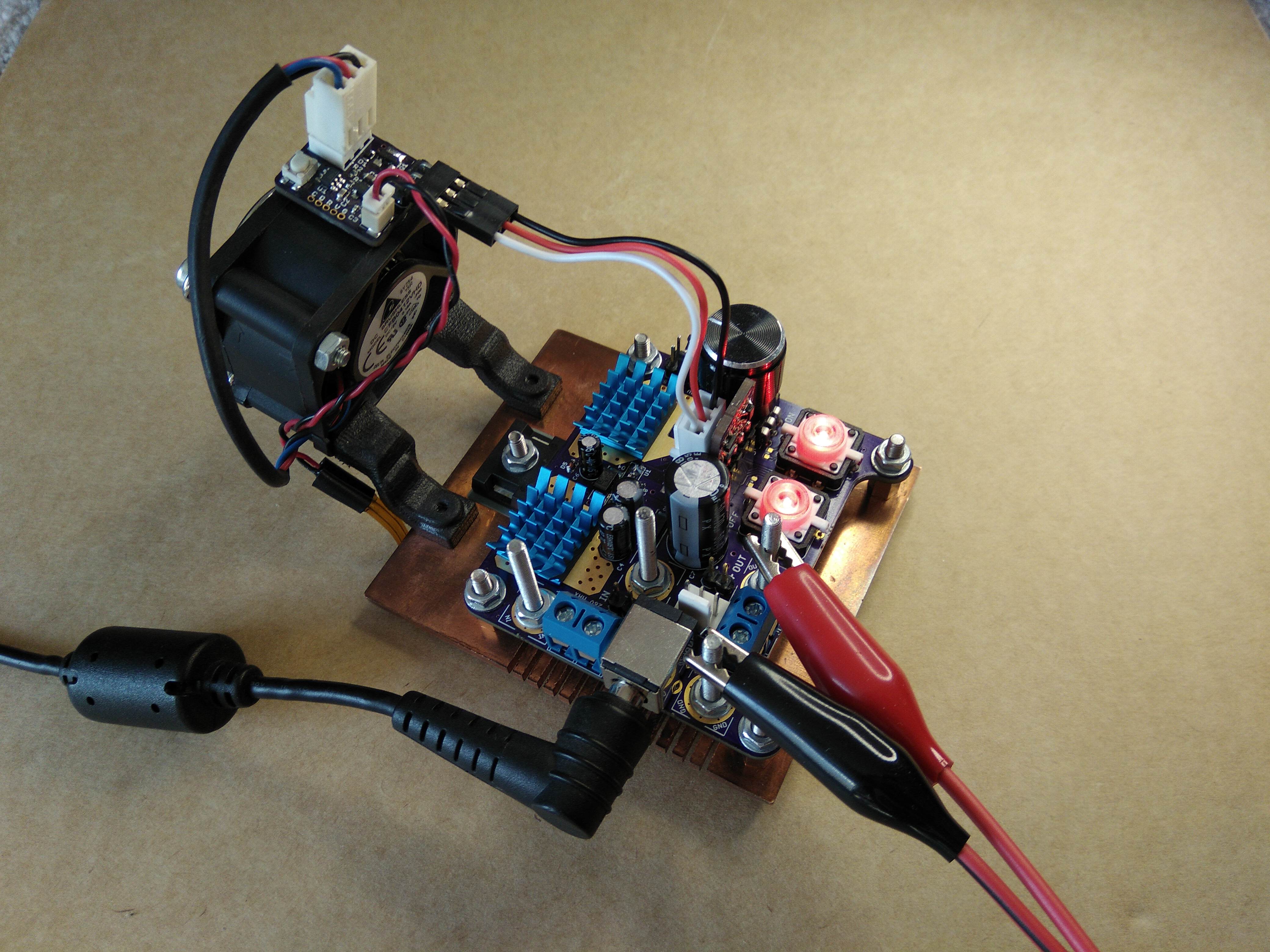
As for the new output power connectors, I’m quite fond of attaching crocodile clips to screws. Screw terminal blocks were also added as well as a few normal pin headers for lower current stuff. The connectors for input power are also similar; screws, terminal blocks and a 2.5mm DC jack for the laptop power supply. I completely forgot about banana plugs; I might have thought about added those too otherwise. There is also a 4th screw near the centre of the board, this is used for bypassing the input diode, if needed.
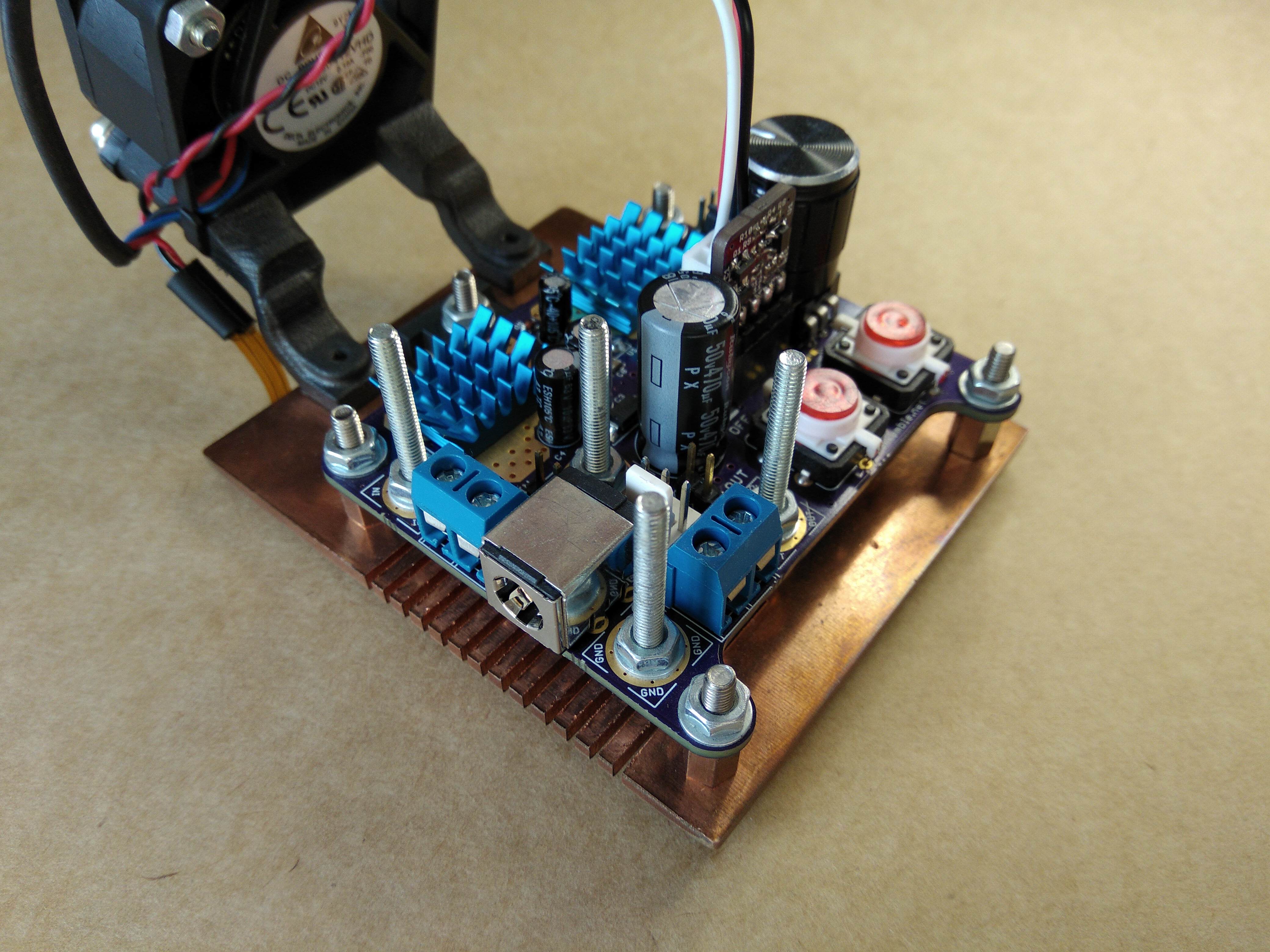
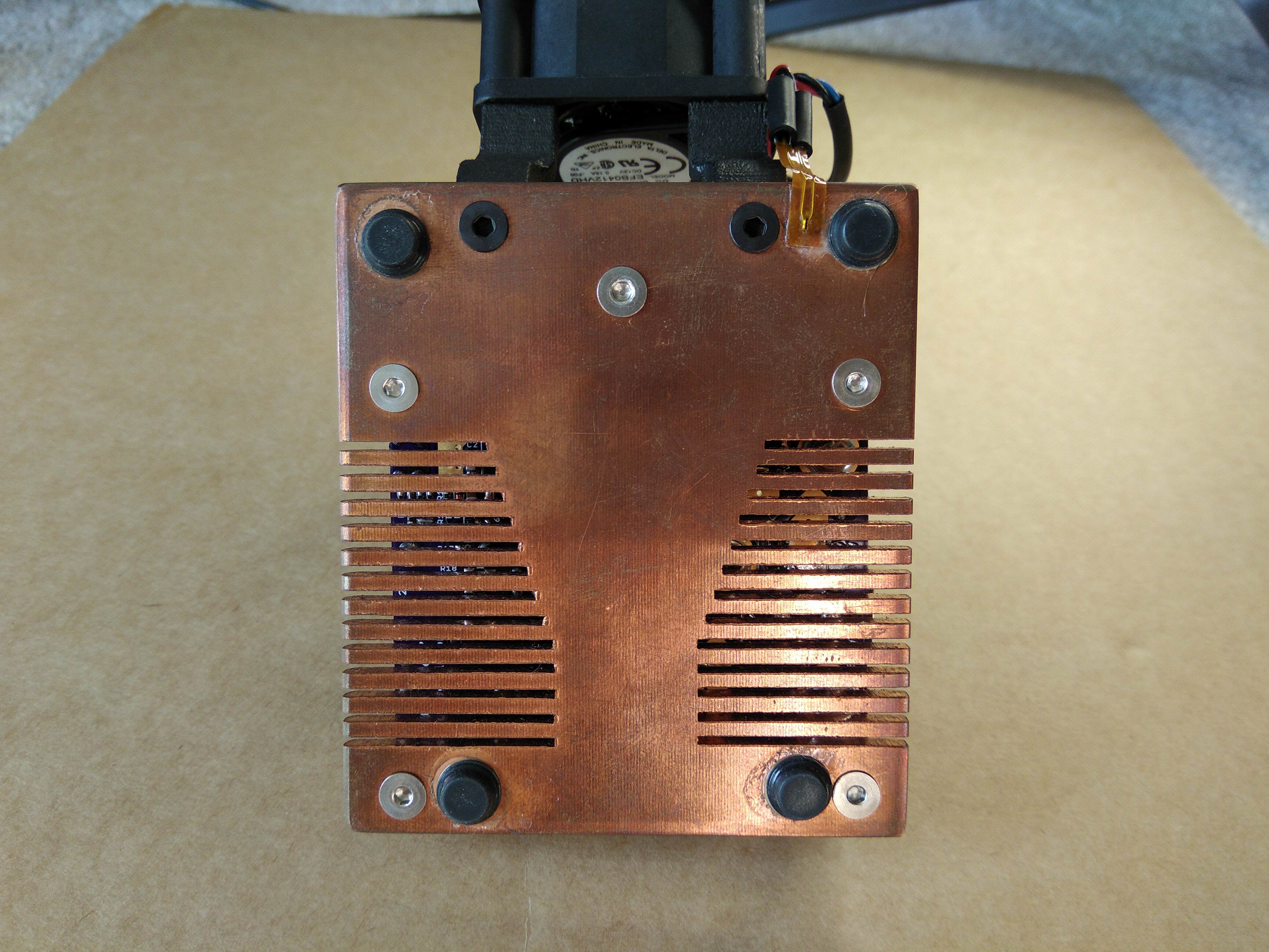
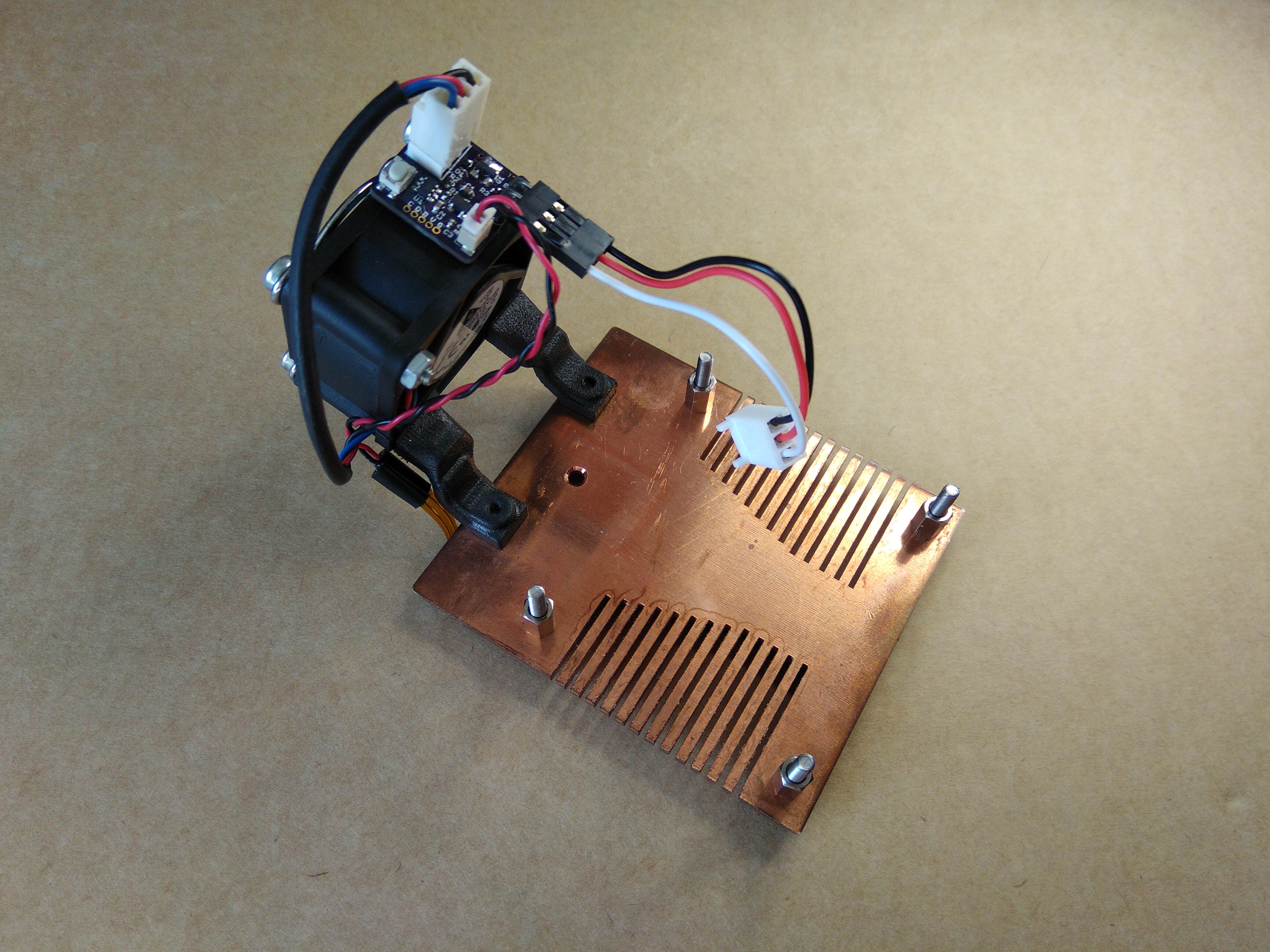
A new custom heatsink was also designed. I wanted the heatsink to be multi-purpose; to be a sturdy mounting point for the PCB, add weight so the power supply doesn’t get pulled around too easily, and of course to keep the regulator cool. I used a 70x78mm 3mm thick copper sheet and drilled a few screw holes for the PCB and regulator mounting and cut some slots out to hopefully help with cooling and to make it look a bit more interesting!
After some testing it turns out that the new heatsink isn’t much better than the older one. It takes longer to heat up since it’s a massive slab of copper with high thermal conductivity and thermal capacity, but its design is not great at passively getting rid of heat.
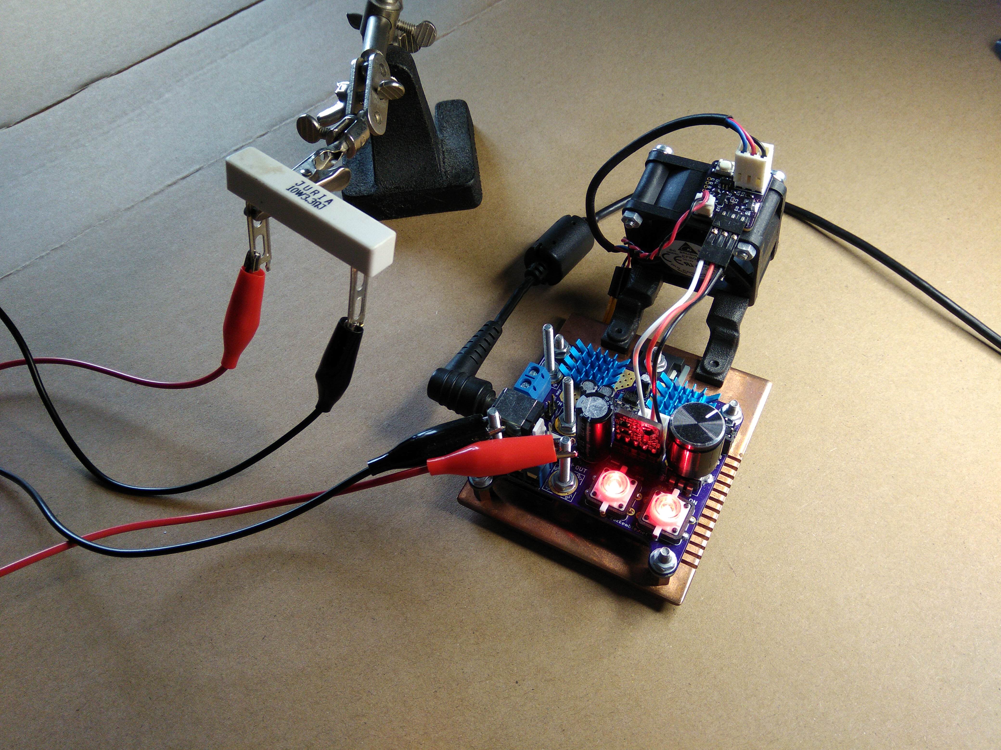
The testing of the heatsink performance was done by using a 3.3R 10W power resistor as a load with the output voltage set to 5V. The thermal limiter of the MIC29752 kicks in it at 125°C, where it begins to lower the output voltage, and thus current and heat dissipation, keeping the junction temperature from going any higher. After a few minutes the output voltage had dropped down to around 2.2V (0.66A through the resistor), and with an input of 19V this would mean the regulator could only dissipate 11.2W while keeping the junction temperature at 125°C. The junction-to-case thermal resistance of the regulator IC is 1.5°C/W, the thermal pad is 0.3C/W and room temperature was 25°C. So, the heatsink has a thermal resistance of (125 – (11.2 \* (1.5 + 0.3)) – 25) / 11.2 = 7.13°C/W. The original heatsink was rated at 7.2°C/W. Soooo it’s a bit of an improvement 😛
The output was still very slowly dropping, but the regulator was slightly oscillating at around 16KHz which was causing the large output capacitor to make a quiet hissing sound so I decided it would be best to stop the test. The LT1083 didn’t have any oscillation problems and could handle temperatures up to 150°C.
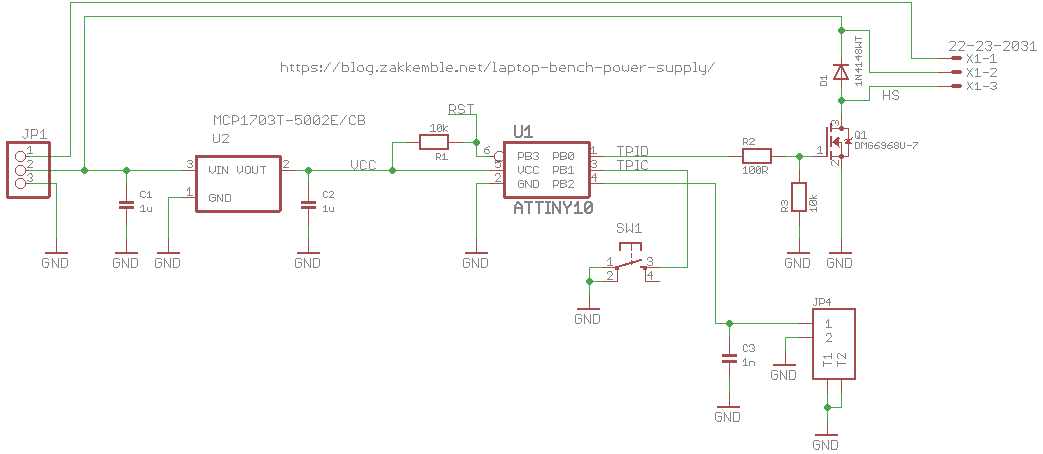
A small fan, actually a rather powerful Delta EFB0412VHD powered by the auxiliary output, was mounted at the back which improved things a lot. A small control board with an ATtiny10 was also made to control the fan based on the heatsink temperature, with a button for selecting auto/on/off.
With the output set to 5.7V, putting 1.7A or almost 10W through the resistor, the regulator had no trouble dissipating 23W. A thermal camera showed that the plastic top of the case was at 68°C (the thermal camera didn’t work on the copper heatsink as it was too reflective). I estimate that the regulator will be able to dissipate around 35W with the fan. The maximum power the regulator can ever dissipate, assuming the case can be held at 25°C, is 66W.
One downside of copper is that it easily tarnishes and loses its shine 🙁 Also the rubber feet adhesive melts when the heatsink warms up.
Overall, it’s a success! It’s much easier to use now that it has screws for attaching crocodile clips to, enough weight to stop it from sliding around the desk and has better cooling with the mounted fan. I’ll have to get around to making the current limiter and displays board sometime, but I think I’ll just buy a real bench power supply, hah!
PCB designs, firmware and things can be found on my GitHub


Comments