DIY Digital Wristwatch
Introduction
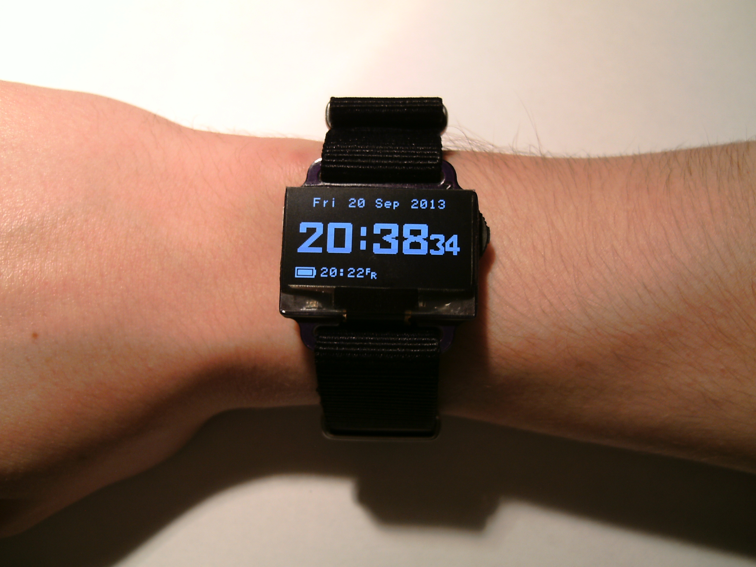
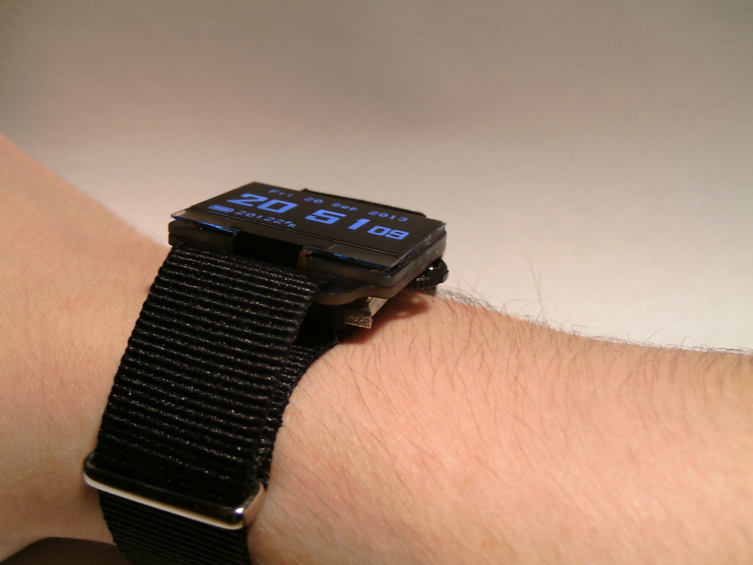
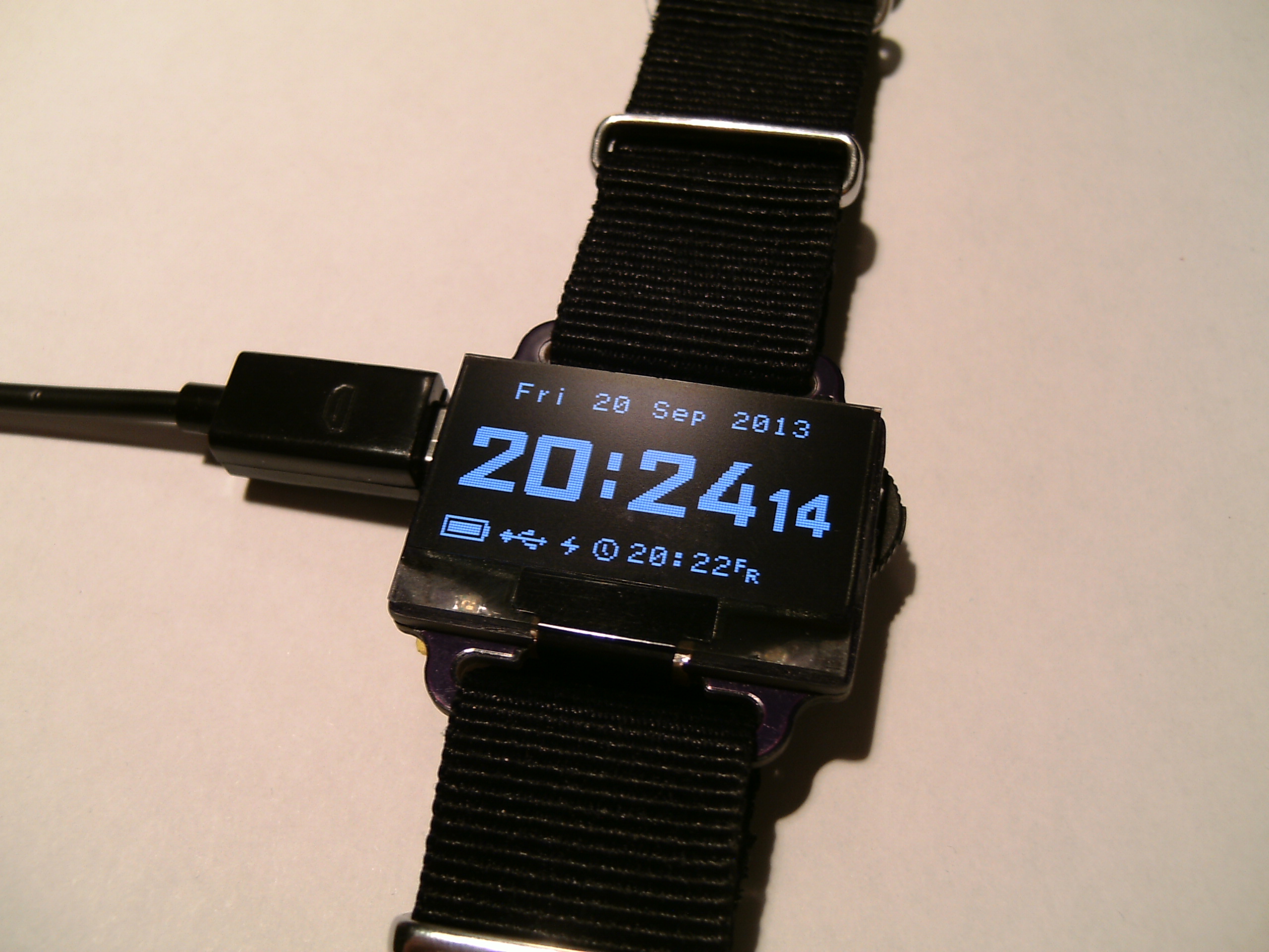
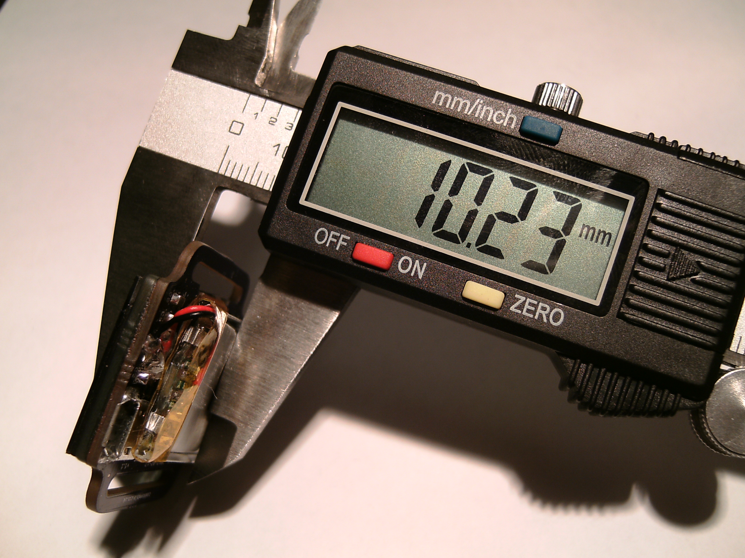
The main incentive behind this project was to see how much I could cram, in terms of both hardware and software, into a wristwatch-like device that is no larger than the display itself. An OLED display was chosen for being only 1.5mm thick and not requiring a backlight (each pixel produces its own light), but mostly because they look cool. The watch was originally going to have a 0.96″ display, but this proved too difficult to get all the things I wanted underneath it. Going up a size to 1.3″ was perfect.
Hardware
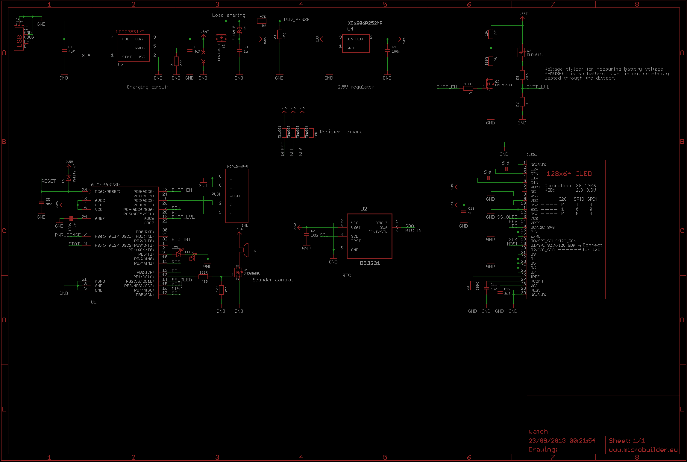
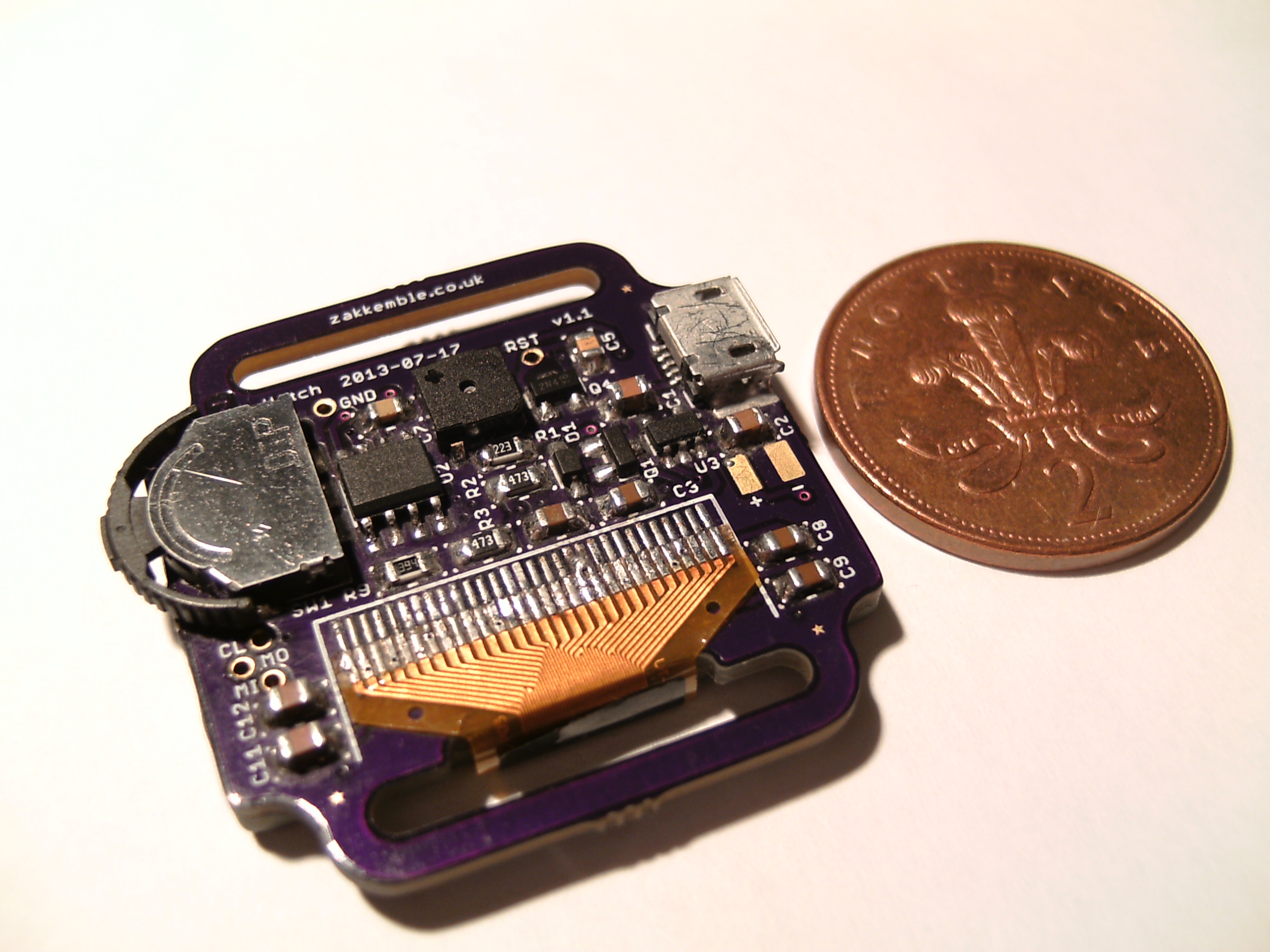
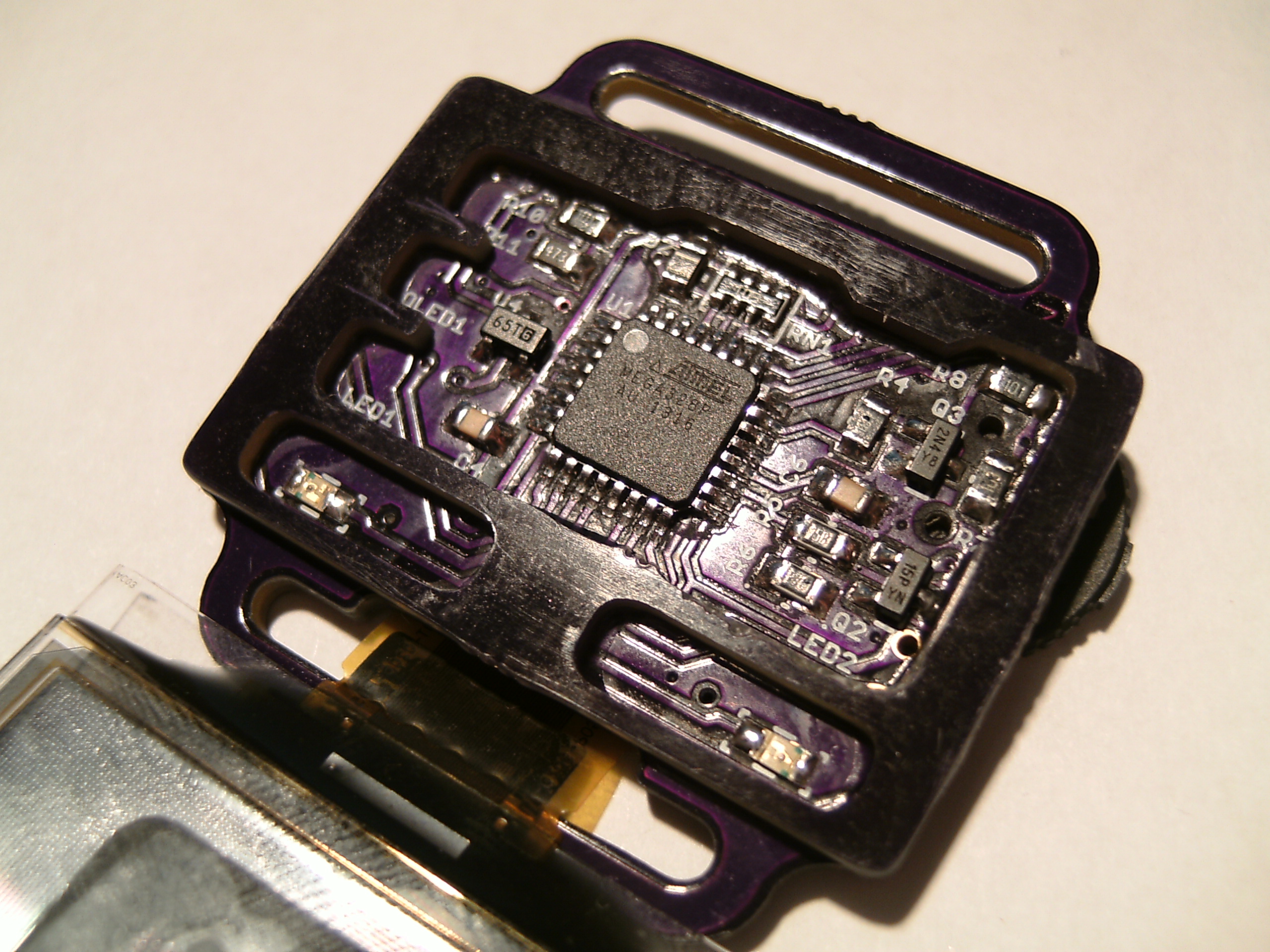
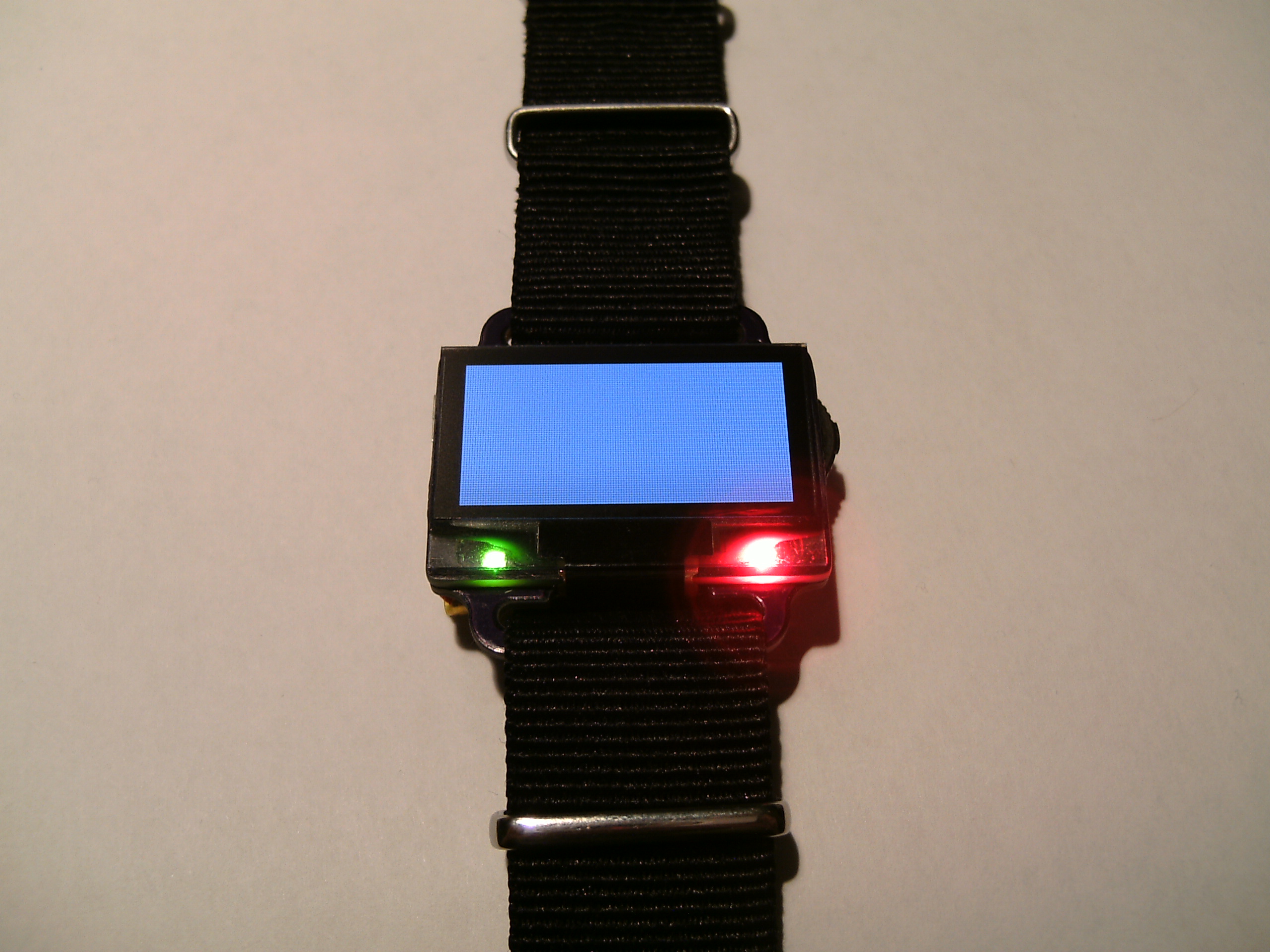
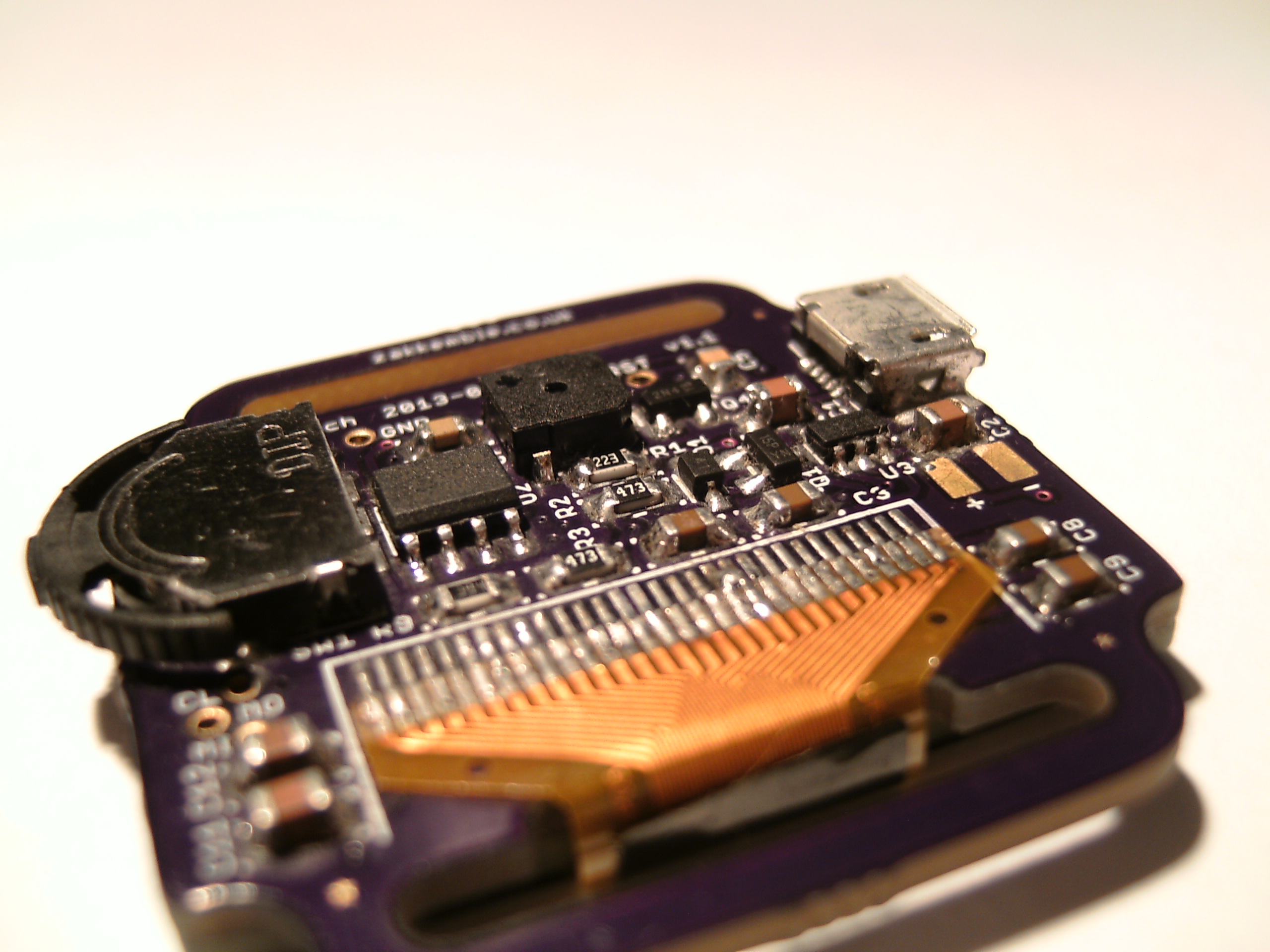
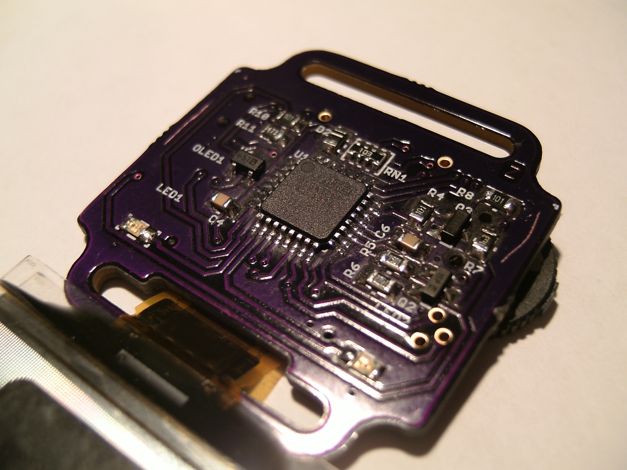
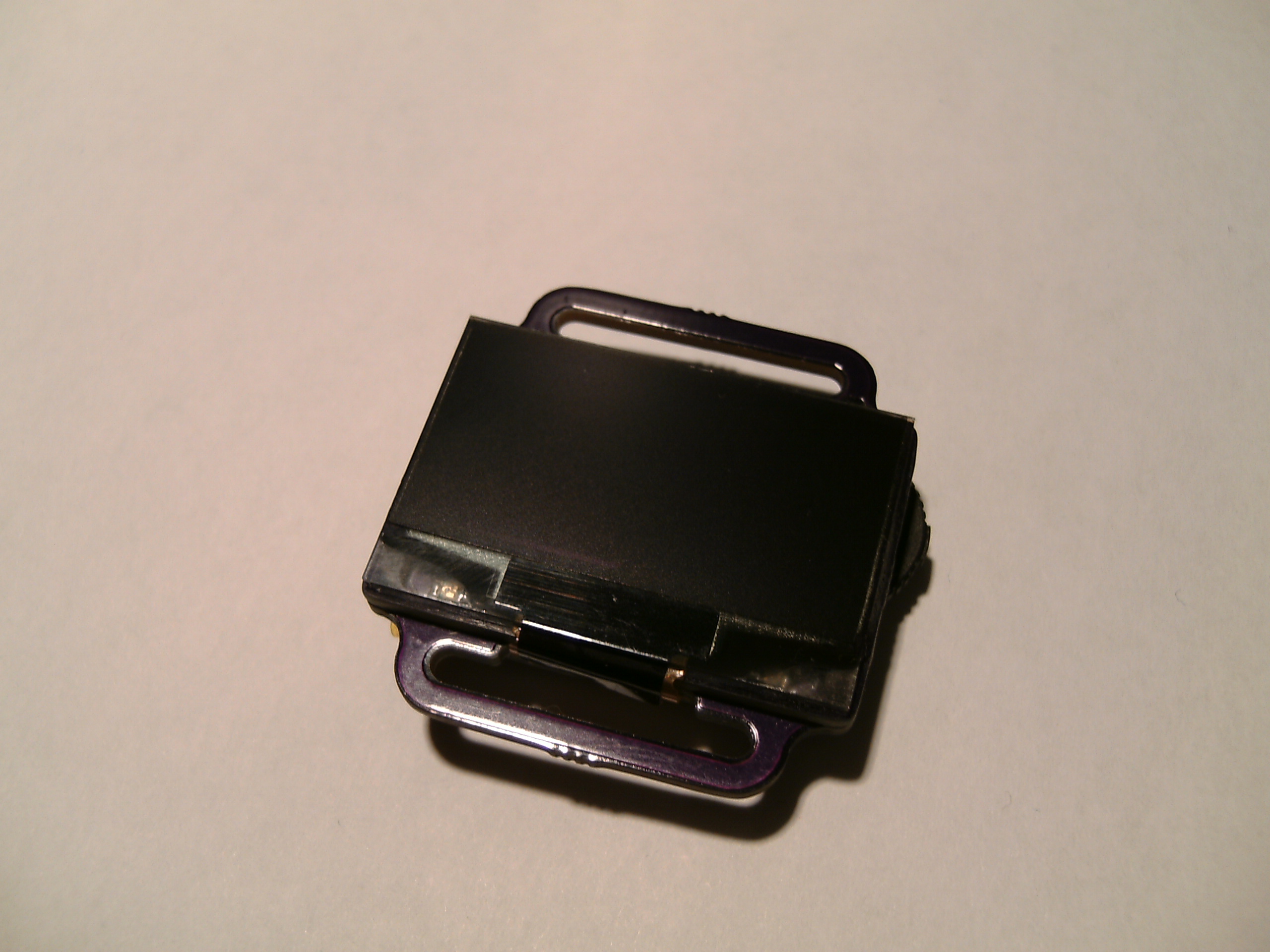
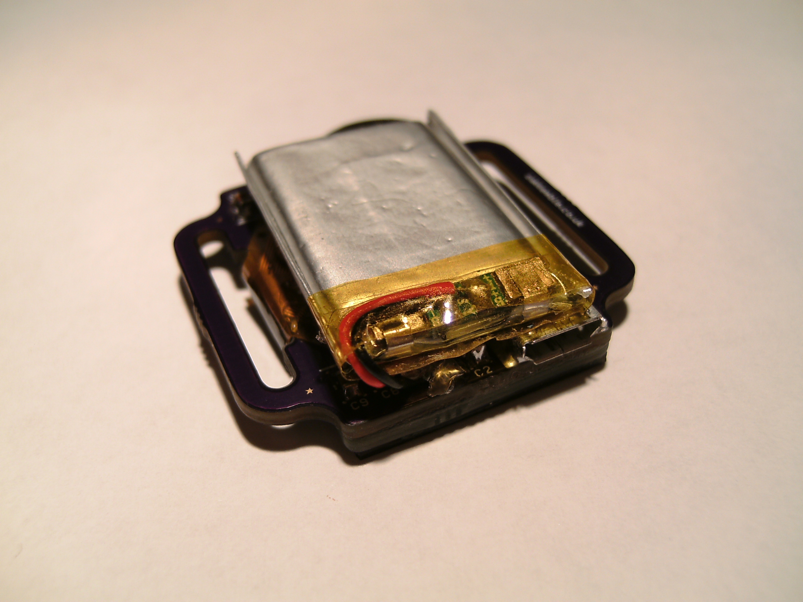
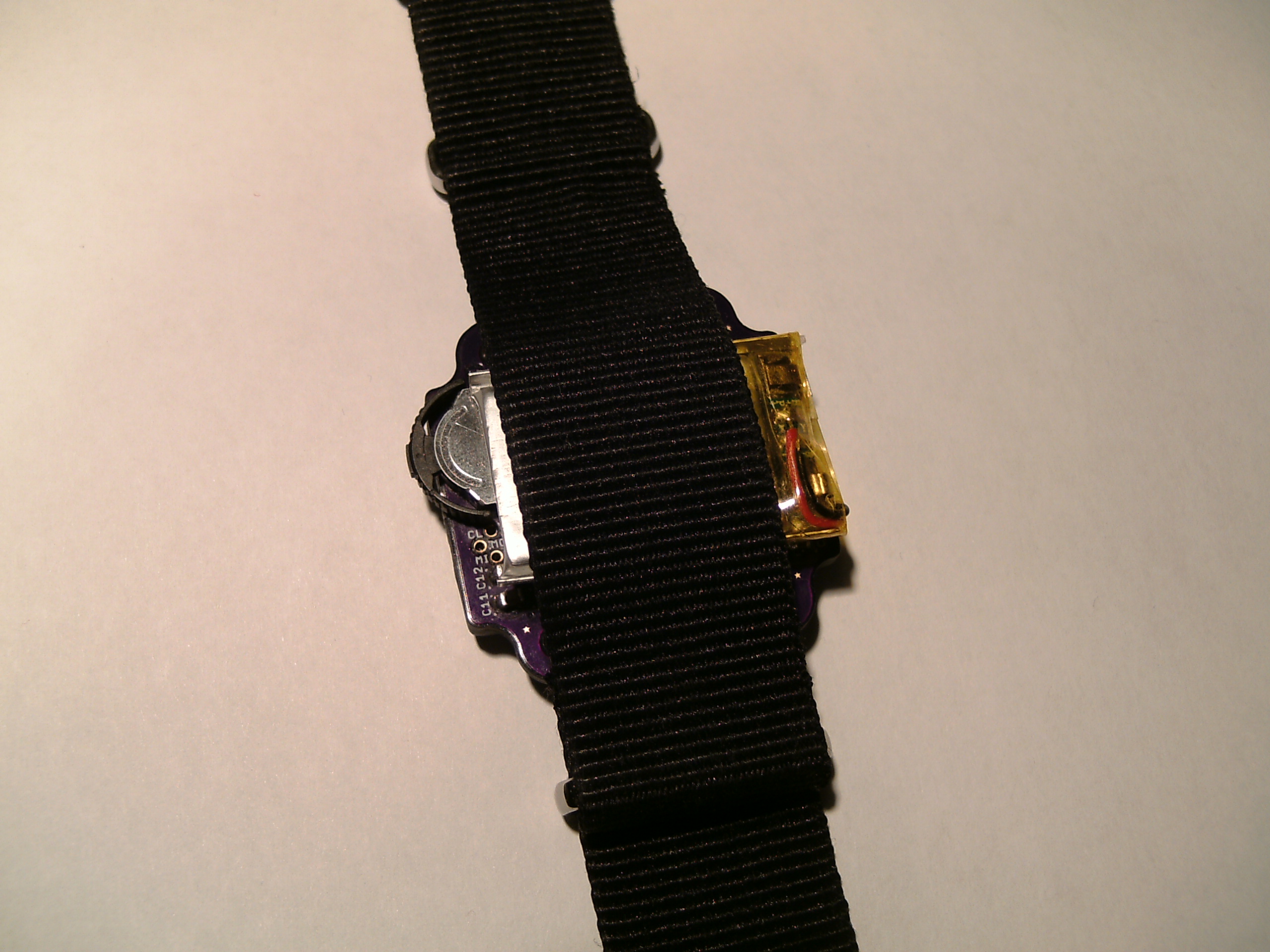
On the hardware side the watch contains an Atmel ATmega328P microcontroller, 2.5V regulator, Maxim DS3231M RTC, 1.3″ 128×64 monochrome OLED, 2 LEDs (red and green), a buzzer sounder, 3 way switch for navigation, powered by a 150mAh LiPo battery which can be charged via USB and 2 PCBs (though one PCB is just used as a raiser for the OLED).
The ATmega328P uses its internal 8MHz oscillator and runs on 2.5V from a linear regulator. Its current draw is around 1.5mA when active and 100nA in sleep mode.
The DS3231M RTC is an excellent chip, housed in a small 8 pin package which includes a built-in temperature compensated MEMS resonator with an accuracy of ±5ppm (± 2 minutes 40 seconds per year). Only a decoupling capacitor and a few extra pull-up resistors were required. The RTC is wired up so that instead of having power applied to the VCC pin, it’s applied to the Vbat pin which reduces its current draw from around 100uA down to 2.5uA.
Unfortunately this chip seems to be very hard to get hold of at a reasonable price if you’re not in the US. I had to get mine as samples.
The battery charging circuit uses a Microchip MCP73832 along with some additional components for load sharing, where the battery can charge without the rest of the watch interfering with it.
You might have noticed in the schematic that the LEDs are directly connected to the microcontroller without any resistors. The internal MOSFETs of the microcontroller have an on resistance of around 40Ω, so with a 2.5V supply voltage and LEDs with 2Vf, around 12.5mA ends up through the LEDs. I would have liked to have a blue LED, but the voltage drop for those are usually more than 3V which would have required some additional resistors and a MOSFET.
As the microcontroller is running on 2.5V the battery voltage needs to be brought down a bit to obtain an ADC reading. This is done by a simple voltage divider. However, with the voltage divider connected across the battery there would be a current of around 350uA constantly flowing through it, this is a huge waste of power. A P-MOSFET (and some voltage level conversion for it, which I forgot about in the first version so it was always stuck on) was added so the divider can be turned on only when needed.
The 2.5V regulator being used is a Torex XC6206, primarily chosen for its tiny quiescent current of just 1uA.
Why a linear regulator and not a switching regulator? The switching regulators I looked at had an efficiency of at least 80% with a 2mA load, but that efficiency quickly dropped off to less than 50% with loads of 100uA. Since the devices connected to the regulator draw 2-3uA in sleep mode, a switching regulator would have performed incredibly poor compared to a linear regulator. The 2.5V linear regulator efficiency is 60% with 4.2V input going up to 83% with 3V input.
Software
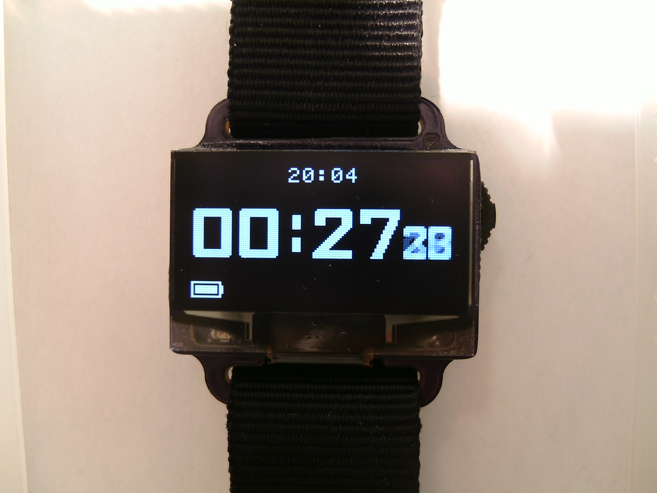
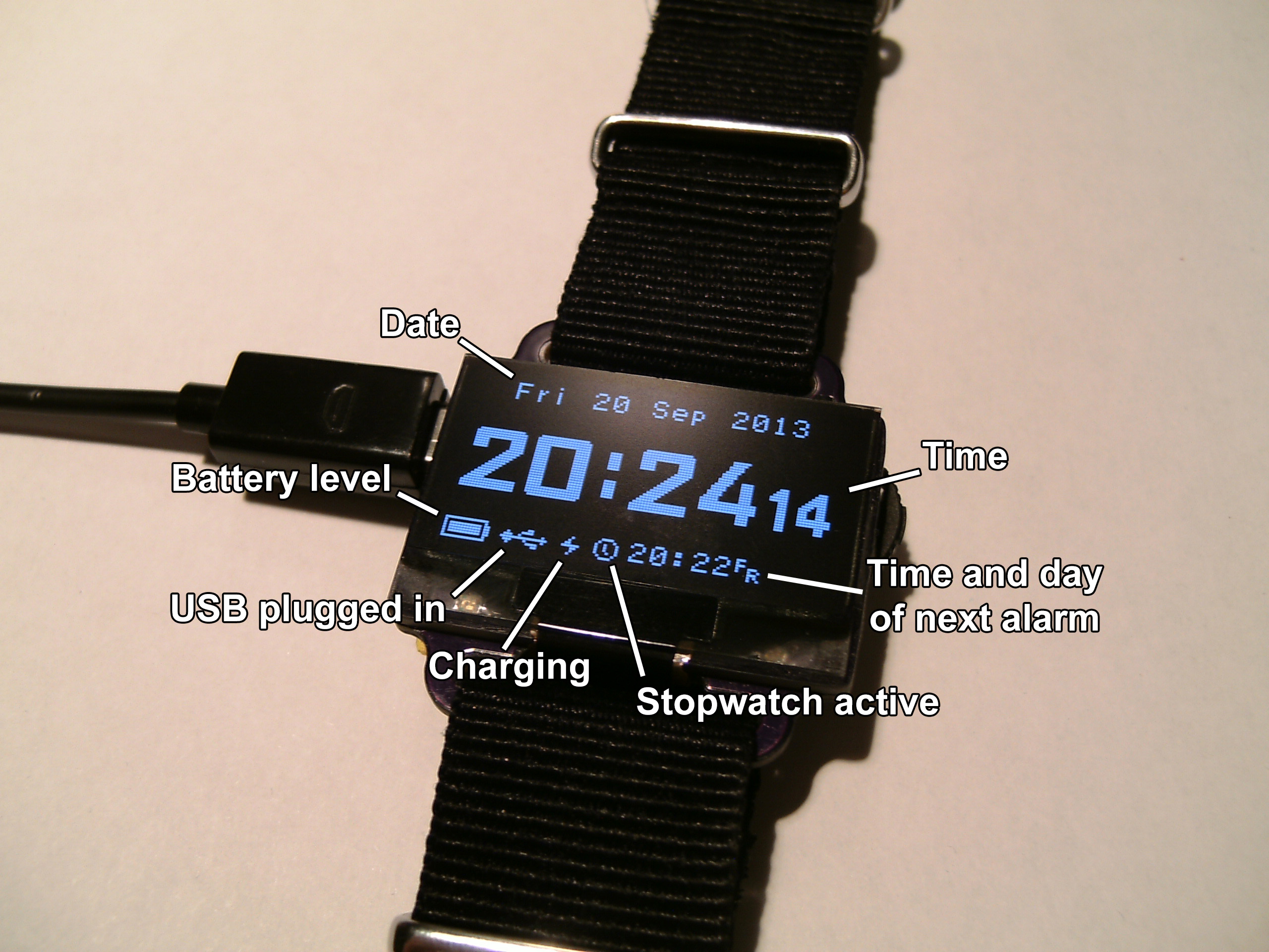
So we’ve got a nice OLED display and 32KB of program space at our disposal, surely we can have more than just the time and date?
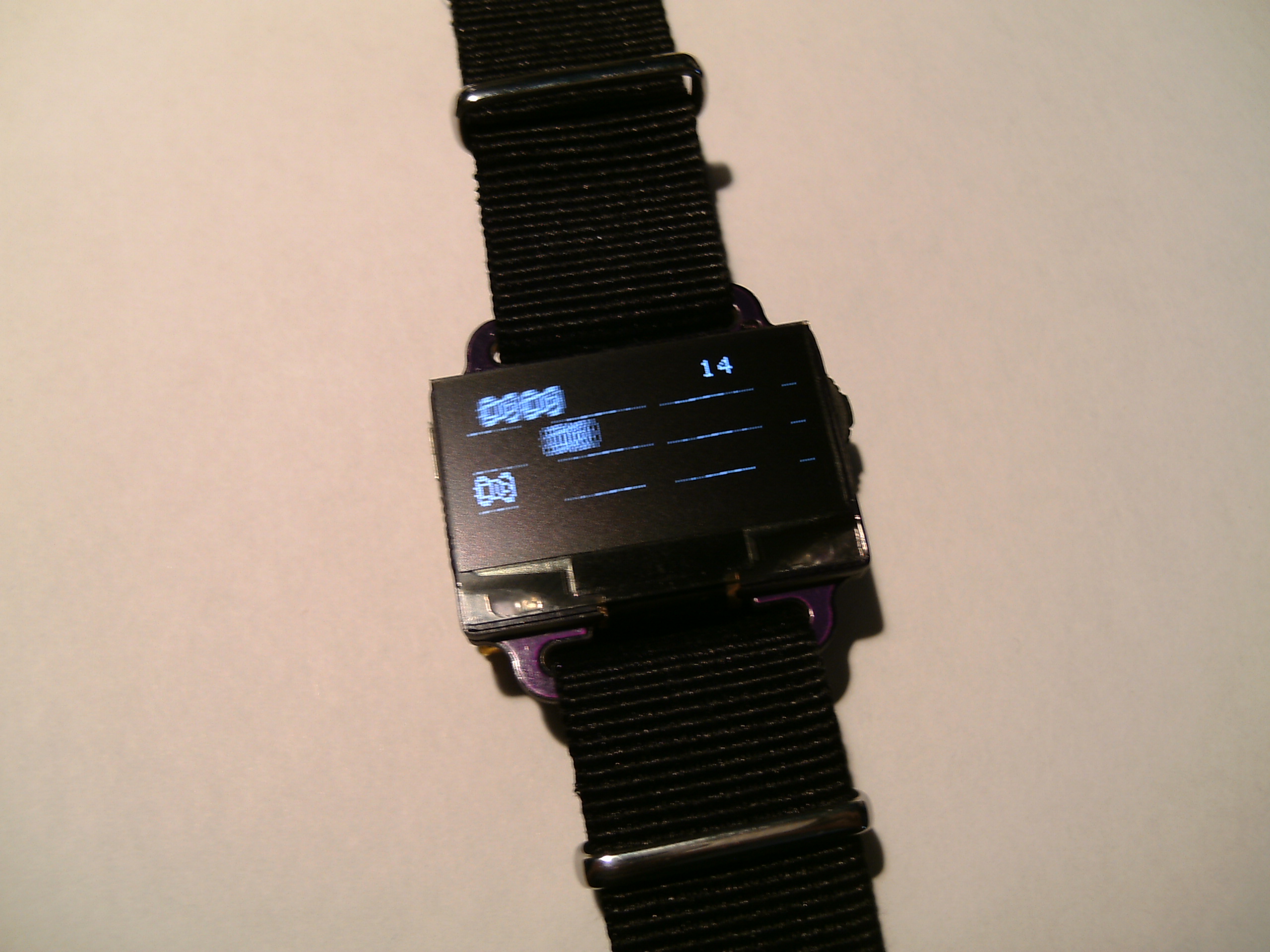
Almost everything is animated
A lot of time was spent optimizing the rendering code which, in short, involves copying bitmap images from flash to the frame buffer in RAM and sending the frame buffer over SPI to the OLED. The end result was being able to maintain 100+ FPS in almost all areas of the watch with an 8MHz AVR. However, since the animations are frame based instead of time based and to save power, the frame rate is limited to 60FPS.
Some of the main animated things:
- CRT animation when entering and exiting sleep mode (similar to the CRT animation that some Android smartphones have).
- Main time numbers have a ticker effect.
- Menus have a scroll left/right animation and selecting an option will cause the current menu to fall off the screen and the next thing to fall on.
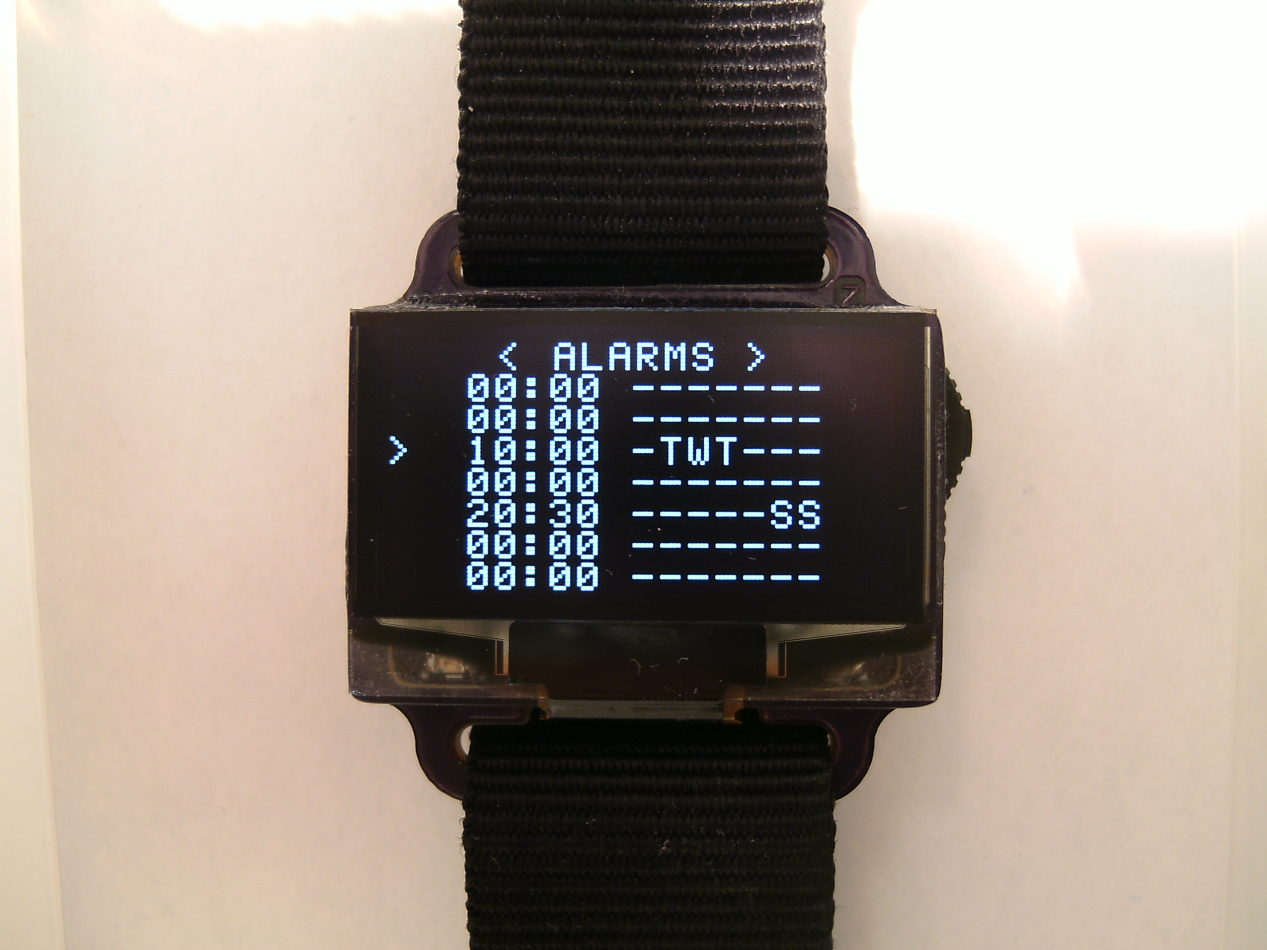
Alarms
- Set up to 10 alarm times.
Number of alarm times is only limited by the amount of available EEPROM - Each alarm has the hour, minute and which days of the week it should be active on.
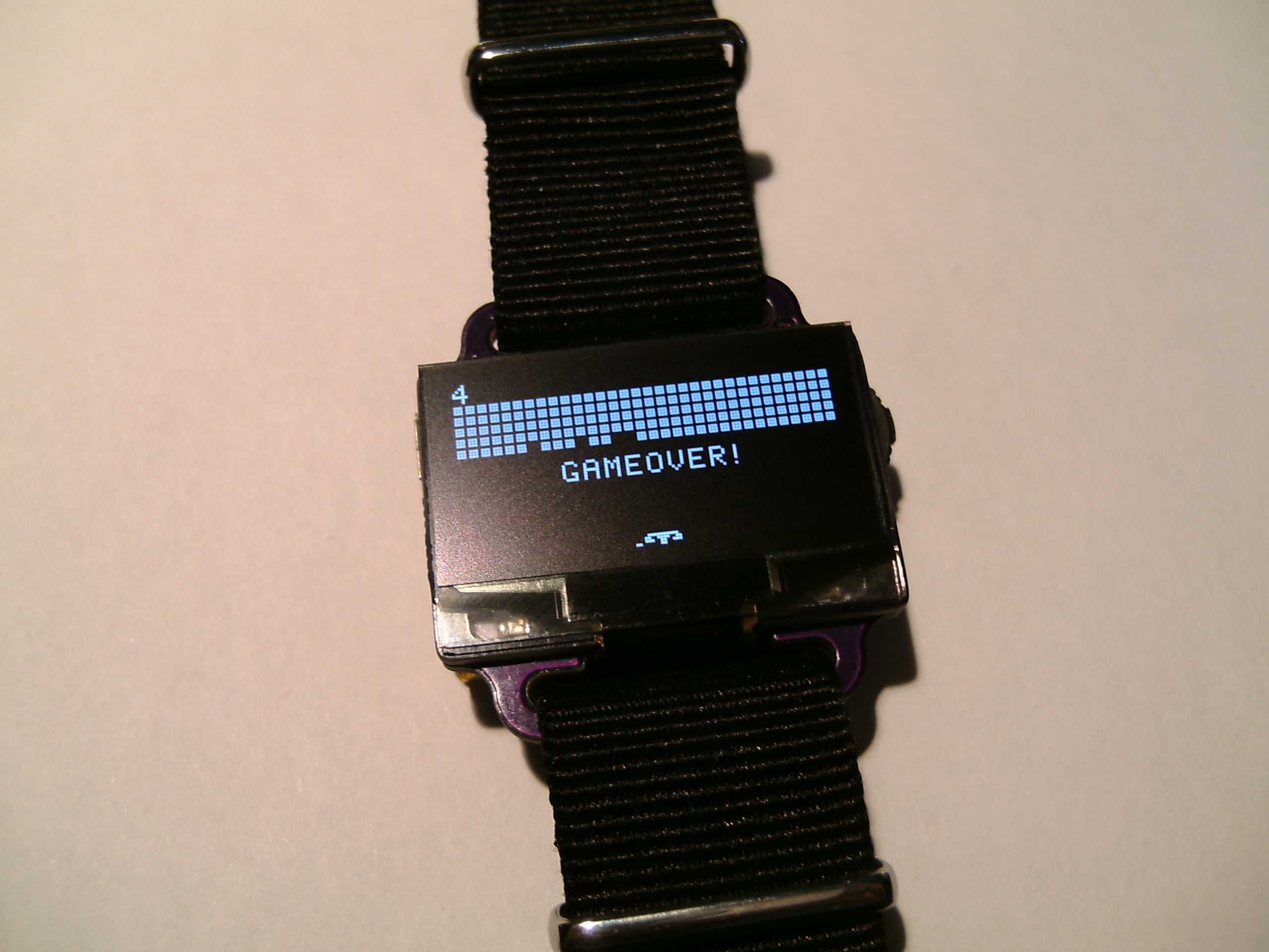
Games
Apps
Turns on all OLED pixels and LEDs,
also has seizure strobe mode
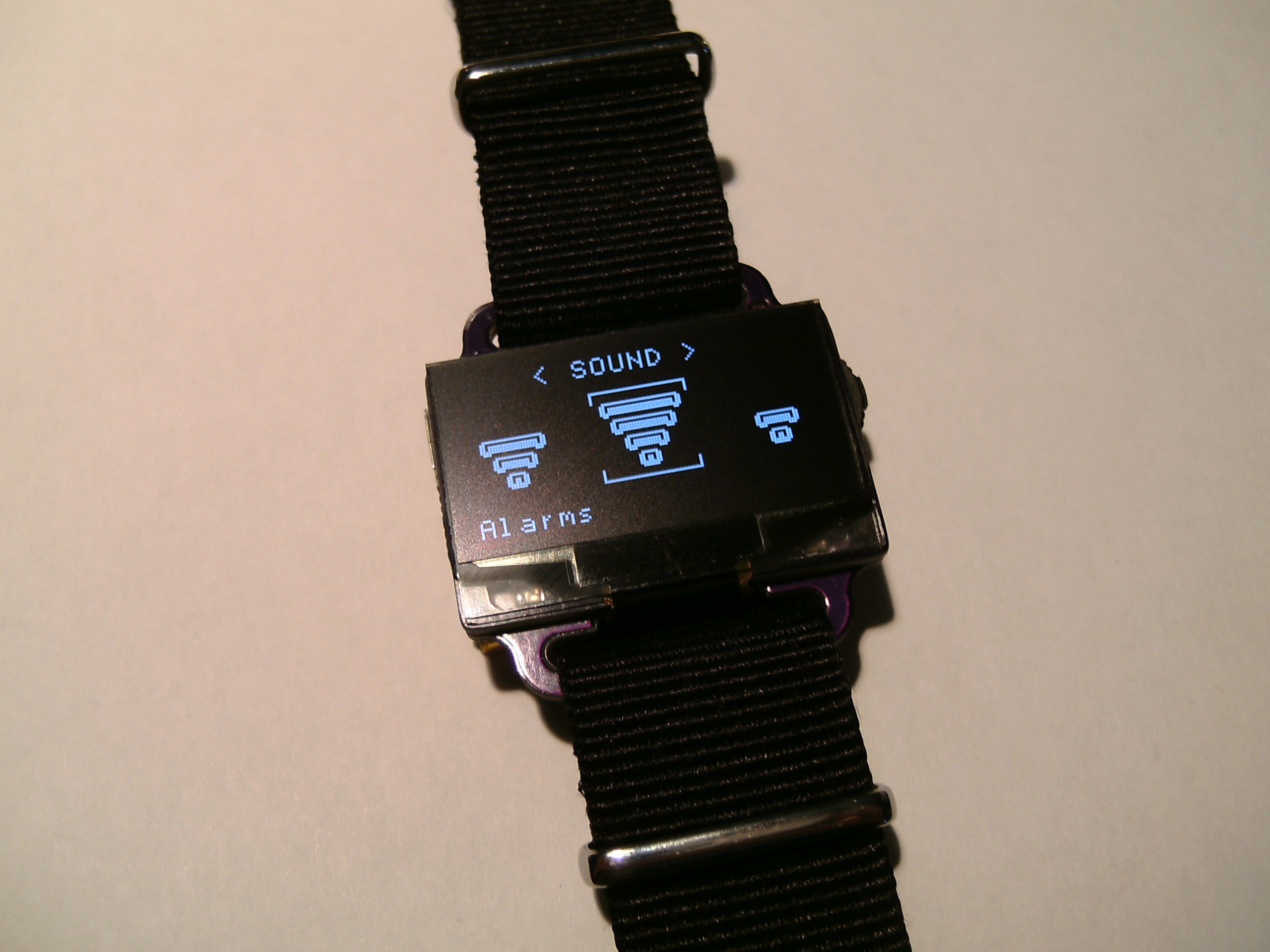
Plenty of options
- 3 Channel volume control
- UI
- Alarms
- Hour beeps
- Sleep timeout
- Display brightness
- Animations
You’re not going to turn them off, right?
Power saving
In ‘active’ mode the microcontroller tries to go into idle sleep as much a possible. In idle sleep the controller is woken each millisecond to see if anything needs to be updated, if not then it goes back to idle sleep, this usually takes less than 100us if the display doesn’t need to be updated. In this mode the current draw can be anywhere between 0.8mA and 2mA, depending on how long it takes to draw frames (fast frame draw time = more time in idle sleep).
In ‘sleep’ mode the microcontroller turns the OLED off and goes into power-down sleep mode where it is only woken by either a button press, an RTC alarm or USB being plugged in. In this state the microcontroller draws ~100nA.
Power Consumption
In sleep mode the overall current draw of the watch is around 6uA. In active mode the current draw can vary from 2mA to over 70mA, though 10mA is the typical current draw.
Battery life in various modes
Battery capacity: 150mAh
| Minimum (sleep mode) |
Typical (main time display) |
High (flashlight) |
|---|---|---|
| 6uA 2.85 years |
10mA 15 hours |
64mA 2 hours, 20 minutes |
If the watch is in active mode for an average of 1 minute per day (with a 5 second sleep timeout that would be checking the time 12 times a day) and all volume channels set to minimum the watch should last for around 1 year and 4 months on a single charge.
Current draw breakdown (typical):
| Part | Current |
|---|---|
| ATmega328P (sleep / active) | 100nA / 1.5mA |
| OLED (sleep / active) | 500nA / 8.5mA |
| DS3231M RTC | 2.5uA |
| Schottky diode (D1) (reverse leakage) | 1uA |
| Regulator (quiescent current) | 1uA |
| Other (MOSFET and capacitor leakage etc) | 1uA |
| Total (sleep / active) | 6.1uA / 10mA |
v1 to v1.1 changes
The first version had a few problems:
- Added level conversion for the ADC P-MOSFET.
Without level conversion the P-MOSFET was always stuck on. To turn of the P-MOSFET off the gate voltage needs to be at around the same level as its source voltage (which is connected to the battery), but the microcontroller was only providing 2.5V. - Added a gate pull-down resistor for the MOSFET driving the sounder.
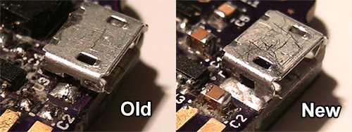
The MOSFET gate was floating when the microcontroller was being programmed which was causing the MOSFET to turn on and allow non-pulsed current to flow through the sounder, which probably wasn’t good for it. - Larger solder pads for MicroUSB connector.
Normally SMD MicroUSB connectors have solder tabs at the sides and should have extra solder pads underneath, but since this is soldered by hand the underneath is unreachable. With out the extra solder pads the USB connector was wobbly so some of the connector pins eventually broke their solder joints. To fix this issue I enlarged the side solder pads so that the connector can be soldered all along its side instead of just the tab. No more wobbly connectors.
Other Problems
Out of 3 OLED displays, 2 died after a few minutes of being attached to the watch. One from Ebay and the other from AliExpress. I’m still not sure why they died, maybe just China quality? The one that worked was also from Ebay.
Future Improvements
- Programming via USB.
At the moment 4 wires need to be poked into the board (SPI programming) and then hope they don’t fall out while programming. - Add a fuel gauge IC.
At the moment the battery level is determined by its voltage, this isn’t a very accurate method of getting the remaining battery charge. - Different microcontroller.
The current firmware is using ~28KB out of the 32KB of available program space in the ATmega328P, a different microcontroller with more program space and probably more RAM would be needed to add more things like a calculator (floating point stuff eats up a lot of program space). However, the ATmega328P has the most program space for an AVR in a 32 pin TQFP package, to have more program space I would have to use a 44 pin AVR. The ATmega1284 looks interesting. - Switching regulator, charge pump regulator or maybe a hybrid solution?
The linear regulator in use at the moment isn’t particularly efficient and switching regulators don’t seem to be very good with low current draw. Perhaps a charge pump regulator or a hybrid solution to swap between a linear regulator for sleep mode and a switching regulator for active mode? - A case of some sort?
Sources available at GitHub
Parts List
| Schematic | Part/value | Description | Quantity |
|---|---|---|---|
| U1 | Atmel ATmega328P | Microcontroller | 1 |
| U3 | MCP73832 | Lithium battery charger IC | 1 |
| U4 | XC6206P252MR | 2.5V LDO Regulator | 1 |
| U2 | DS3231MZ+ | RTC | 1 |
| Q1, Q2 | DMP1045U | P-MOSFET | 2 |
| Q3, Q4 | DMG6968U | N-MOSFET | 2 |
| D1 | ZLLS410 | Schottky diode | 1 |
| D2 | TS4148 | High speed diode | 1 |
| C5 | 4.7nF | Capacitor | 1 |
| C4, C6, C7 | 100nF | Capacitor | 3 |
| C3, C8, C9, C10 | 1uF | Capacitor | 4 |
| C12 | 2.2uF | Capacitor | 1 |
| C1, C2, C11 | 4.7uF | Capacitor | 3 |
| R4, R8, R10 | 100R | Resistor | 3 |
| R6 | 2.7K | Resistor | 1 |
| R5 | 7.5K | Resistor | 1 |
| R7 | 10K | Resistor | 1 |
| R1 | 22K | Resistor | 1 |
| R2, R3, R11 | 47K | Resistor | 3 |
| R9 | 390K | Resistor | 1 |
| RN1 | 10K network | Resistor network (4x resistors) | 1 |
| LED1 | LED (green) | LED | 1 |
| LED2 | LED (red) | LED | 1 |
| LS1 | Sounder | Magnetic sounder | 1 |
| SW1 | 3 Way navigation switch | - | 1 |
| - | MicroUSB connector (Ebay) | - | 1 |
| OLED1 | OLED (Ebay / AliExpress) | - | 1 |
| - | Battery (Ebay) | - | 1 |
| - | Main PCB | - | 1 |
| - | Display raiser PCB | - | 1 |
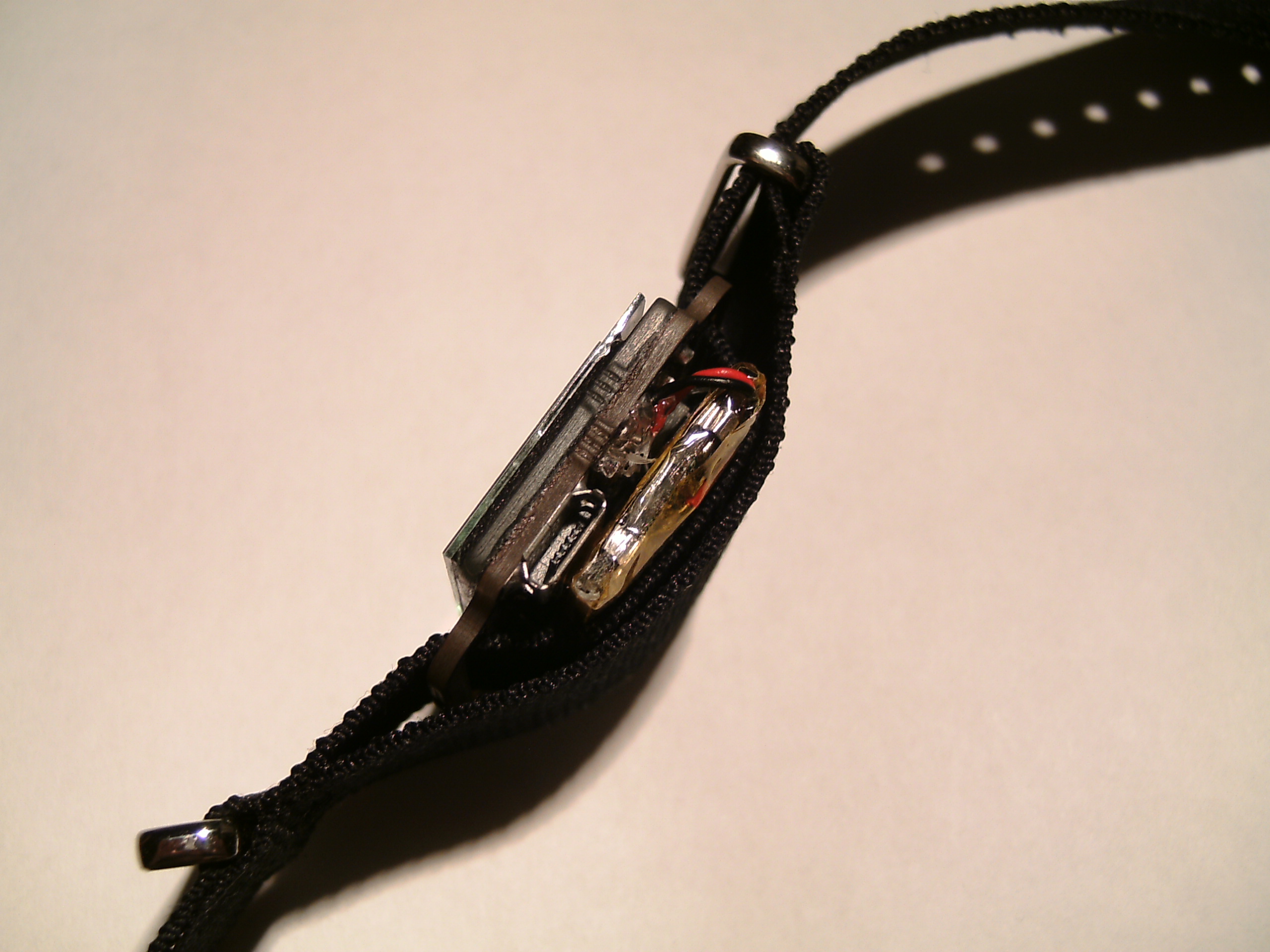
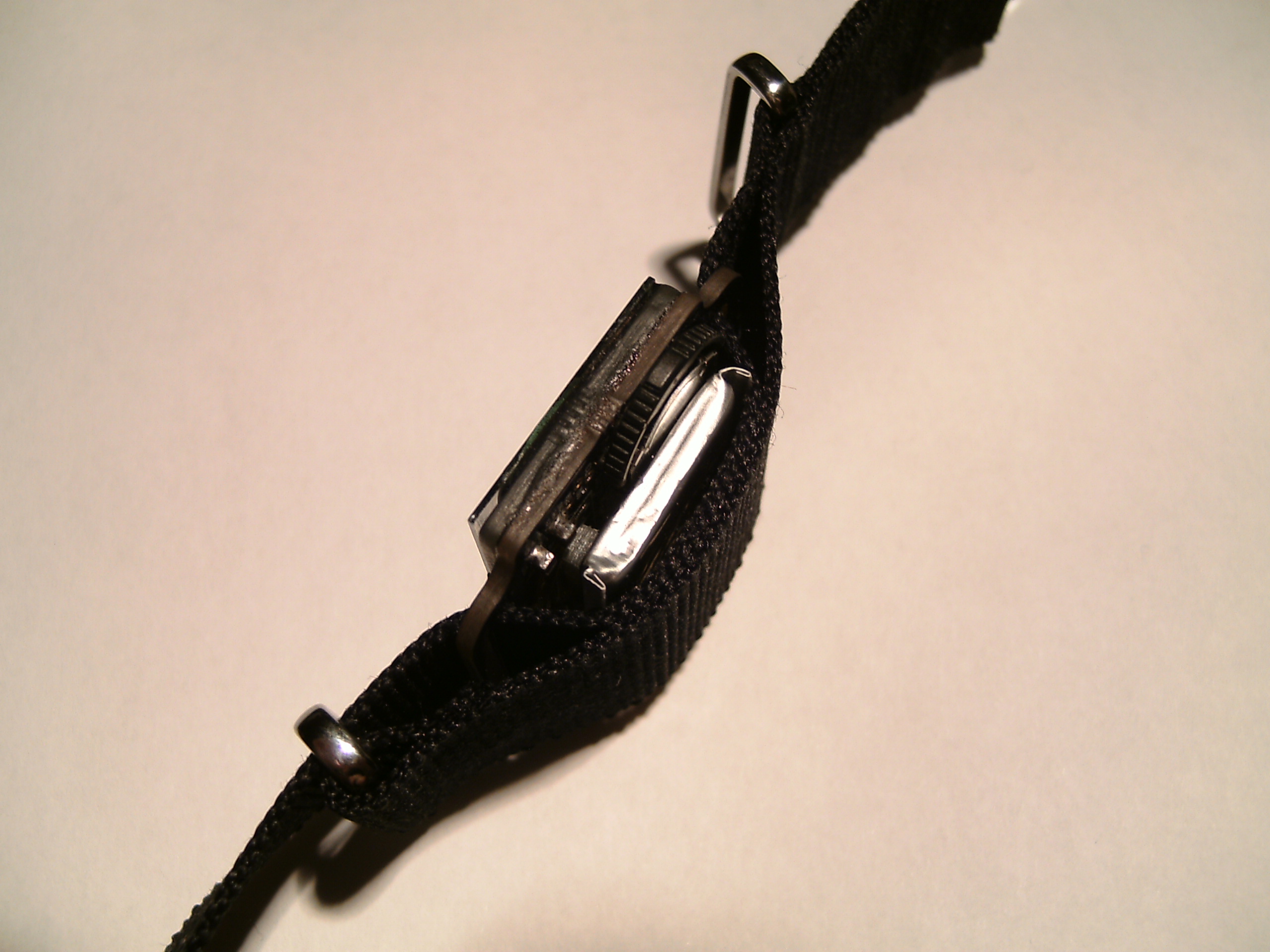
| - | Watch strap | G10 NATO 22mm | 1 |
Featured at
Atmel, HackADay,Electronics Lab, adafruit
Water proof down to 0m!

Comments