MCP2221 HID Library
This is a library for interfacing with the HID features of the MCP2221 USB to UART and I2C/SMBus serial converter from Microchip and the newer MCP2221A. The converter includes 4 GPIO pins, 3x 10-bit ADCs, 1x 5-bit DAC and more.
Microchip does provide a library for interfacing with the chip, however it is supplied as proprietary DLLs. This project aims to be an open-source and multi-platform alternative.
This library also makes use of HIDAPI.
Supported features:
| Feature | Status |
|---|---|
| ADC | Supported |
| DAC | Supported |
| GPIO | Supported |
| Interrupt input | Supported |
| Clock reference output | Supported |
| USB Descriptors (Manufacturer, product, serial, VID, PID) |
Supported |
| I2C/SMB | Limited support, WIP |
| Flash password protection | Not yet implemented |
| C++ and C# wrappers | Not yet implemented |
Download from GitHub
Documentation
Bits of info about the MCP2221
- Doesn’t use a crystal, only requires 1 small capacitor when powered with 3.3V or 2 capacitors when powered with 5V.
- Available in a hacker friendly DIP package.
- Has a remote wake function which when used in conjunction with the interrupt input can be used to wakeup the USB host (usually a PC), just like waking up from a keyboard or mouse press.
- The raw value of the I2C pins can also be read, allowing them to be used as an additional 2 general purpose input pins.
- Unfortunately there are no options for enabling any internal pull-up/down resistors.
- The MCP2221 seems to be a PIC16F1455. [Source]
- Current consumption @ 3.3V with USB disconnected can be anywhere between 20uA and 70uA, not sure what causes such a difference. Remote wakeup needs to be disabled (default) otherwise current consumption will be about 5mA.
- Kinda slow compared to other USB/UART converters. Even with the baud rate set to 1,000,000 its overall throughput is only about 250,000 bps. More about this below.
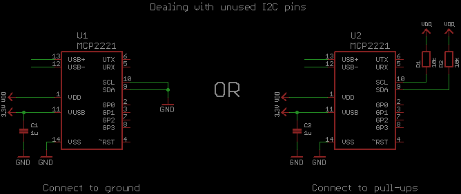
Unconnected pins
The usual way to deal with unconnected pins are to enable their internal pull-up/down resistors, but this chip doesn’t support them. Instead it’s probably best to set unconnected pins as output high or low.
The I2C pins are a little different since they can’t be set to outputs, though there’s still few options:
| I2C Pin | Description |
|---|---|
| Unconnected | Bad, floating inputs will cause excessive power consumption |
| Connect to VDD | Bad, if the I2C bus is accidentally used then a short circuit will occur |
| Connect to ground | OK, but may cause the I2C bus to hang if used, not much of an issue though |
| External pull-up resistors | Best option, but requires additional components |
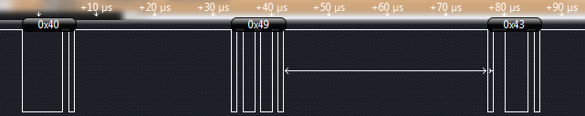
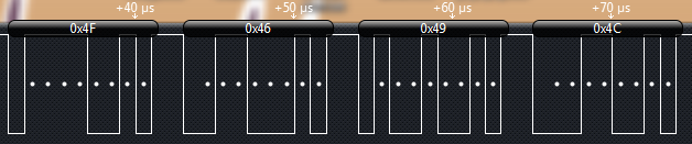
UART Throughput
The main UART function seems to be really slow, maxing out at about 250,000 bps throughput when set to 1,000,000 baud due to a gap of about 30us after each byte transmitted. This isn’t much of a problem at lower bauds, but as the baud rate increases it creates a huge overhead (75% @ 1Mbaud!). Attempting to receive data without a sufficient gap will also corrupt the data. Here are some screen shots comparing the MCP2221 and CH340 UART converter ICs transmitting data at 1,000,000 baud. The MCP2221 has a gap of about 30us between each byte, while the CH340 has a gap of just 1us.
Other issues
If the MCP2221 receives too much UART data too soon after powering up it will have trouble enumerating with the USB host.
MCP2221A
The MCP2221A replaces the MCP2221 and is fully compatible with this library. The new chip appears to have fixed the USB enumeration issue described above and the gap between each transmitted UART byte now varies from 4us to 18us, but usually around 6us.
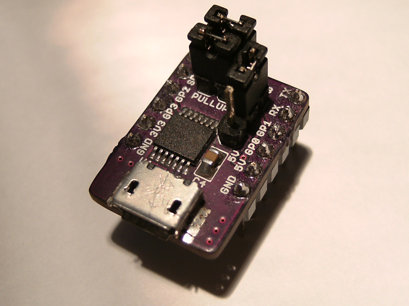
design available on the GitHub repo

Comments