The nRF905 is a radio transceiver IC similar to the well known nRF24L01, but operates at 433/898/915MHz instead of 2.4GHz, has a much longer range and a few extra IO pins. However, the nRF905 data rate is only 50Kbps compared to nRF24L01’s 2Mbps.
This library offers quite a bit of flexibility: Optional use of interrupts, 2 of the connections to the module are optional since their states can also be accessed by the ICs status register, and supports basic collision avoidance.
NOTE: v3.0.0 of the library was released on 12th September 2017, the default CD pin has changed and the AM pin is now used by the library.
Download:
Arduino – Documentation (or use the Arduino library manager, search for “nrf905”)
AVR (non-Arduino) – Documentation
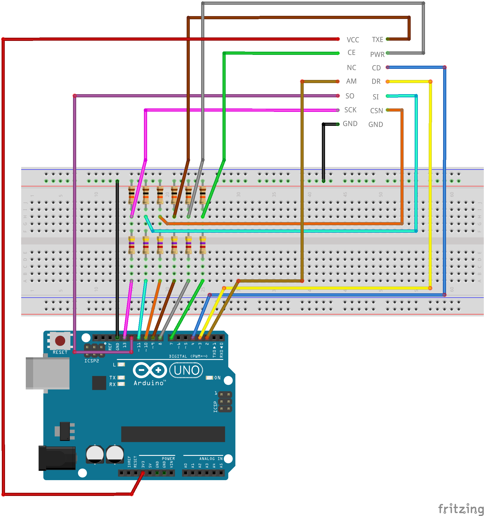
nRF905 | ATmega48/88/168/328 | Arduino Uno | Description |
---|---|---|---|
VCC | 3.3V | 3.3V | Power (3.3V) |
CE | D7 (13) | 7 | Standby – High = TX/RX mode, Low = standby |
TXE | B1 (15) | 9 | TX or RX mode – High = TX, Low = RX |
PWR | B0 (14) | 8 | Power-up – High = on, Low = off |
CD | D4 (6) | 4 | Carrier detect – High when a signal is detected, for collision avoidance |
AM | D2 (4) | 2 | Address Match – High when receiving a packet that has the same address as the one set for this device, optional since state is stored in register, if interrupts are used (default) then this pin must be connected |
DR | D3 (5) | 3 | Data Ready – High when finished transmitting/High when new data received, optional since state is stored in register, if interrupts are used (default) then this pin must be connected |
SO | B4 (18) | 12 | SPI MISO (Mega pin 50) |
SI | B3 (17) | 11 | SPI MOSI (Mega pin 51) |
SCK | B5 (19) | 13 | SPI SCK (Mega pin 52) |
CSN | B2 (16) | 10 | SPI SS |
GND | GND | GND | Ground |
Some of the module pin names differ from the IC pin names in the datasheet:
Module | IC |
---|---|
CE | TRX_EN |
TXE | TX_EN |
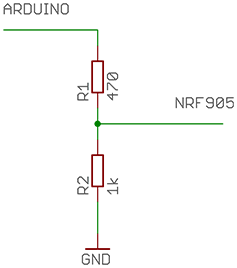
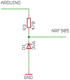
The nRF905 is not 5V compatible, so some level conversions will need to be done with the Arduino outputs. A simple voltage divider or resistor and zener diode will do the trick. Only TXE, CE, PWR, SI, SCK and CSN pins need level conversion (not CD, AM, DR and SO).
Divider | Zener |
---|---|
![]() |
![]() |
The nRF905 has 511 channels ranging 422.4MHz – 473.5MHz in 100KHz steps on the 433MHz band and 844.8MHz – 947MHz in 200KHz steps on the 868/915MHz band (remember to check which frequencies are legal in your country!), but each channel overlaps adjacent channels so there are only a total of 170 usable channels at once.
Searching for nRF905, PTR8000 and PTR8000+ should yield some results for modules on AliExpress, Ebay and DealExtreme. You should be able to get 2 for around £10.
Callbacks
Since v3.0.0 this library uses callbacks which are ran when events occur. If the option to use interrupts is enabled then the callbacks will run from the interrupt routine so be sure that any global variables you use in them are declared ‘volatile’, just as you would when dealing with normal ISRs. These events will wake the microcontroller if it is sleeping.
Event | Callback | Notes |
---|---|---|
New packet incoming | NRF905_CB_ADDRMATCH | |
Valid packet received | NRF905_CB_RXCOMPLETE | |
Invalid packet received | NRF905_CB_RXINVALID | |
Packet transmission complete | NRF905_CB_TXCOMPLETE | This only works if the nextMode is NRF905_NEXTMODE_STANDBY when calling nRF905_TX() |
Nitty-gritty radio stuff
The actual air data-rate of nRF905 is 100Kbps, but the data is Manchester encoded which halves the throughput to 50Kbps. The modulation is GFSK with ±50KHz deviation. The radio also adds a few extra bits of data to the address and payload; a preamble and CRC.
Preamble 10 bits |
Address 1 or 4 bytes |
Payload 1 – 32 bytes |
CRC 0 – 2 bytes |
The address is also used as the syncword and should have as many level shifts as possible. 10100110 01100101 00011010 11011010 (2791643866) would be a good address to use, but 00000000 00000000 00000000 0010000 (32) would not be.
The CRC is used to detect errors in the received data. Having a CRC doesn’t eliminate all bad packets, there is always a small chance of a bad packet passing the CRC. Using larger CRCs helps to reduce that chance.
When the CRC is set to 16 bit the radio uses the CRC16-CCITT-FALSE (0xFFFF) algorithm. I’m not sure what it uses for 8 bit CRCs.
Transmission time
The sizes of the address, payload and CRC can be adjusted for a balance between throughput and latency.
Address size | Payload size | CRC size | = | Throughput (bps) | Latency (ms) |
---|---|---|---|---|---|
4 | 32 | 2 | = | 36940 | 6.93 |
1 | 4 | 1 | = | 17680 | 1.81 |
1 | 1 | 0 | = | 6838 | 1.17 |
Throughput is how much useful data can be sent (the payload part), assuming no delays for writing and reading the payload.
Latency is how long it takes for the transmission to complete.
Switching from standby mode to receive or transmit mode takes a maximum of 650us and switching between receive and transmit modes takes a maximum of 550us.
Transmission time can be worked out with:
tstartup is the time to switch mode as stated above (650us / 550us).
tpreamble is 200us for the 10 bit preamble.
Naddress, Npayload and NCRC are the address, payload and CRC sizes in bits.
BR is the bit rate which is 50,000.
For config 1, switching from standby to transmit:
t = 0.00693 seconds (6.93ms)
A note to developers: Before v3.0.0 this library would load the address bytes in reverse order, keep that in mind if you’re using an old version of the library to interface with other radio systems!
607 comments
3 pings
Skip to comment form
Hello!
About “nRF905 AVR/Arduino Library/Driver” : can you help me? I have KL-NRF905 radio transceiver and 2 pins a not the same (your rf905-se have NC and CD, my module have vCLK and CO), how i can connect this one to my arduino using your library?
Thanks a lot!
I have one mistake: my “CO” pin is “CD”. But i have uCLK or vCLK, what to do with it? Maybe it is Groud (i haven’t GRD pin) ?
Author
uCLK can be used a a clock source for the AVR chip, if you’re not using it then leave it disconnected.
Look for a pin that is connected to a large copper trace that goes around most of the PCB, that one is probably GND.
Thanks for the very fast reply! just found the datasheet and a little began to get involved in the subject. Even read the datasheet to find about the ground
Sorry for so many posts, but here’s a picture and data from the Datasheet. Are the legs of the ground:
http://s1.ipicture.ru/uploads/20130209/kET1UYgy.jpg
maybe someone will be useful
Author
Yup, the red dots are the ground connections. The bottom 2 pins of the module are GND, but they’re not labeled.
Thanks again for the information. Your article is the only one I could find on this topic, in the evening I’ll try modules in action!
Hi! And how can I check whether I have plugged the nrf950 to the controller?
Author
The library doesn’t have that feature, but I can make a function for you to add to your code to see if its connected, are you using Arduino for this?
Yes, i use arduino and I doubt the connection
Author
Oh, do you mean you’re not sure it’s connected correctly (its not working) or do you want to see if it’s actually connected to the Arduino using code?
Yes, i’m not sure it’s connected correctly and I want to interview the connection of the module from arduino
Author
Ah right, sorry for the confusion, a mistake I kept doing was connecting CE and TXE the wrong way around, a photo will help my see how it’s wired. Also if you’re using the ping server/client examples it should print to serial things like “Client started” and “Ping timed out” from the client.
it should print to serial things like “Client started” and “Ping timed out” from the client
yes, it is, then all right? Probably, not connected correctly the second module
Author
Timing out doesn’t mean its transmitting or connected correctly, it just means the code is working.
and I had time to experiment with the module.
connection is successful, the ping is normal.
came the question: how to pass an array of characters? setdata function in the first parameter of type char, which can be done to pass a string?
Thank you!
Author
Yup, when you pass the char array you will need to typecast it to
byte*
, only 32 characters can be sent at a time since that’s the maximum payload size.char myStr[] = "test test";
nRF905_setData((byte*)myStr, sizeof(myStr));
Yes. I try this way, but client writes “JBIJ….JBIJ…JBIJ” to terminal if i send “TEST” and “zbyz zbyz” =))) if i send “test test”…
it is a problem with char to byte and byte to char convertion…But it’s really cool that i send some information!
Author
There shouldn’t be any problems with converting between char and byte. It seems that the last 4-5 bits of each character are not what they are meant to be, maybe the serial baud rate isn’t quite right?
I try change serial baud rate and no result.
If I try
char myStr[] = “test”;
nRF905_setData((byte*)myStr, sizeof(myStr));
AND
nRF905_getData(buffer, sizeof(buffer));
if( (char*)buffer)==”test )
Serial.print(“!”);
no result…
Author
You’re comparing strings wrong, what you’re doing there is checking if 2 variable pointers are the same, not if the string is the same. You need to compare each character individually which can be done using strcmp().
nRF905_getData(buffer, sizeof(buffer));
if(strcmp((char*)buffer, "test") == 0)
Serial.println("OK");
else
Serial.println("Fail");
Oh….Yes….We work with pointers….And why i have wrong output data in Serial?
Thanks!
Author
Does serial also output the wrong data when trying some of the Arduino serial examples?
Hello,
I’m new with Arduino.
I’m using the arduino 1.04 programming software in LinuxMint 14 and the I have an Arduino Leonardo board, how can I correctly load the nRF905 library? I downloaded it as a .zip and I extracted it in the “libraries” directory but when I load an exemple and I try to verified it, the arduino is giving me this errors:
In file included from /home/super/Scrivania/arduino-1.0.4/libraries/nRF905/nRF905_spi.h:11,
from /home/super/Scrivania/arduino-1.0.4/libraries/nRF905/nRF905_spi.c:8:
/home/super/Scrivania/arduino-1.0.4/libraries/nRF905/nRF905_types.h:19: error: expected specifier-qualifier-list before ‘byte’
In file included from /home/super/Scrivania/arduino-1.0.4/libraries/nRF905/nRF905_spi.c:8:
/home/super/Scrivania/arduino-1.0.4/libraries/nRF905/nRF905_spi.h:16: error: expected ‘=’, ‘,’, ‘;’, ‘asm’ or ‘__attribute__’ before ‘inline’
Thanks.
Author
Hey, I think you copied some of the wrong files, for Arduino you copy the files from
.zip/master/arduino/
toarduino-1.0.4/libraries/nRF905/
, the other files are for non-Arduino stuff.Thanks Zak. Now it is working!
Hi, i am new at this, i hope you can help me.
I bought a nRf905se and this receiver at dx: http://dx.com/p/diy-433mhz-wireless-receiving-module-for-arduino-green-149252. Can i send data to the receiver using the nRF905? How about setting the address of the receiver, is it possible?
thanks
Author
No, nRF905 and the linked module won’t work together. That module is a ‘dumb’ radio, it doesn’t have any sort of digital radio chip so it doesn’t have an address, it just spits out whatever it receives (the chip on it is a comparator). The virtual wire library will work with it, once you get a matching transmitter.
Hi! I was able to connect the module and work through it with the information, thank you for your scheme and the library!
Hi,
I am new at wireless communication, I hope you can help me in getting started.
Please correct me, if I am wrong, your libraries will only work with UNO but not with Mega boards?
If that’s the case, are there any modifications required to make it work on Mega?
Appreciate, if you can also share PIN connection for that as well.
Regards,
Author
Hey, the library should work for the Mega boards, but some pin numbers are different:
SO -> 50
SI -> 51
SCK -> 52
You’ll also need to edit nRF905_config.h a little bit, near the bottom change the following:
INT1 -> INT5
INT1_vect -> INT5_vect
EICRA -> EICRB
((1<<ISC11)|(1<<ISC10)) -> ((1<<ISC51)|(1<<ISC50))
**EDIT** The info about nRF905_config.h changes is for an old version of the library. You now only need to set INTERRUPT_NUM to 5.
Hi!
I have successfully been using your library for sending and receiving.
Now, the question arose: how to scan all channels in the presence of a signal from another device?
That is, found in the air at 433 MHz unknown device and get information from it …
Ps that’s what I do: find a few trinkets from the old alarm, I want to use them in new ways.
Author
You can use
nRF905_setChannel(NRF905_BAND_433MHZ, channel);
ornRF905_setFrequency(NRF905_BAND_433MHZ, 433200000);
to change channel/frequency between 422.4MHz and 473.5MHz, each channel is 100KHz apart,channel
should be a number between 0 and 511. When changing channel/frequency you need to give it a about 10ms (I think) to settle then see ifnRF905_airwayBusy()
returns true. However to actually receive data the transmitter must use GFSK modulation, data rate of 100Kbps with Manchester encoding, frequency deviation of ±50KHz and the packet format must be|Preamble (10 bits)|Address (4 bytes)|Payload (1-32 bytes)|CRC (2 bytes)|
. Most alarm systems use OOK modulation with a data rate much below 100Kbps, no Manchester encoding and a different packet format. You could use radio modules that use the CC1101 chip, it offers many more features like setting which modulation to use (2FSK, 4FSK, GFSK, ASK/OOK, MSK). You could also have a look into SDR (software defined radio).Hello Zak,
I hope you can help me. I’m doing my dissertation work (to be presented this week) on nRF905G (it only works between 844.8Mhz and 947.2Mhz) and Arduino Leonardo.
I have already modified the code from your page (I owe you a beer btw) for my frequency but my question remains now with 2 headers:
AM – I didn’t connect it with the Arduino since I saw it is optional but in the code it was declared. Do I need to connect it?
Anything else I should change besides the frequency for my project to work? I’m doing the transmission part and one of my colleagues is handling the reception.
Thanks,
Mihai
Author
Hey Mihai,
Leave AM disconnected, it’s declared in a few places but not used by any of the core code.
There shouldn’t be anything else you need to change, follow the examples and you should be fine 🙂
Thanks Zak !
One more question, perhaps you can help me. If I want to put an audio channel also, meaning to transmit to the reception something like: “hey man, stop the clock, the runner fell ” how should I do it?
Should I connect the microphone to a digital pin on the leonardo? What would be the code for this?
If you have knowledge on this please let me know ! The beers are on me like I said 😉
( we are simulating a photo-cell timmer for sport contests ).
Author
You would connect the microphone to an analog pin, but the ATmega32u4 is not designed for audio, the maximum ADC sample rate is around 15KHz producing 120Kbps if using 8 bit resolution. You then need to send this data using the nRF905 with a data rate of 50Kbps which includes preamble, address and CRC so you only end up with around 40Kbps using a 32 byte payload. On the receiving end you will need a DAC. In the end you will end up with something pretty much inaudible.
I see, well know I have more theory to put in my dissertation paper. Thanks Zak !
Hi,
Does this module really need all 9 connections?
I thought the NRF parts had automatic collision detection etc, or is that sort of functionality only in the 2.4Ghz modules?
Can most of the functions be done via SPI
Thanks
Author
Hey,
DR and AM are the only two optional connections since the status of those pins can be checked by reading the status register, however AM isn’t used by the library so no need to connect it anyway. CE, TXE, PWR and CD must be connected since the radio IC doesn’t have any registers that allow reading or writing the state of those pins.
The nRF905 doesn’t have any automatic collision detection, the nRF24 ICs do all that stuff automatically as well as retransmissions and acknowledgments.
Other than the pin setting and reading everything else is done over SPI.
Zak,
Thanks for the explanation.
Cheers
Roger
Hi! Thank you for your answers and help!
I have a question again 🙂
Developing the theme of nr905: I use Arduino Mega + nrf905 + TFT LCD
Can you please tell how to use nr905 and LCD (I mean the ISP protocol)
Connect all devices stage at some ports, or each use a separate SPI SS?
How, then tweak the library to use the right pins?
How to implement this on the mega? Thank you!
Author
Only the MOSI, MISO and SCK pins can be shared between SPI devices. All other connections need their own pins. Pin settings for the nRF905 library are in nRF905_config.h, for the LCD you set the pins when calling the class constructor.
Good afternoon. I want to transfer CD and DR from 2 and 3 pins to 11 and 12 Arduino Mega. In all nRF905_config.h adjusted as necessary.
The module works with but one oddity:
No signal on the receiving end of the DR, if I close 2 and then 3 pin, the signal appears on the receiving end and the reception is successful.
As I understand it is interrupt 2->3 pines?
Which interrupt to use for data ready on 11 and 13 pins?
Do not tell me how to implement the mechanism on 11 and 12 pines?
Maybe use attachinterrupt?
As I understand it is written in nRF905_config.h, lines 71-80?
Thank you!
I solve this problem:
#define NRF905_INTERRUPTS 0
#define NRF905_DR_SW 1
Thanks a lot for library!
Author
That’s one of solving it, but may not be what you want. Setting NRF905_DR_SW to 1 means you don’t need DR connected anymore, but it becomes slightly slower.
CD can use any pin, but DR needs an external interrupt pin. On the Mega you can choose from pins 2 (INT4), 3 (INT5), 18 (INT3), 19 (INT2), 20 (INT1) and 21 (INT0). You will also need to update the register settings to correspond with the interrupt number you’re now using.
For example, if you use pin 18 (INT3) you will have to use these settings:
#define BIT_EXTERNAL_INT INT3
#define INT_VECTOR INT3_vect
#define BIT_EXTERNAL_INT_CTL ((1<<ISC31)|(1<<ISC30))
No problem 🙂
If I use DR to pin 18, the program does not respond, even setup does not send anything to the serial port.
Using
# Define NRF905_INTERRUPTS 0
# Define NRF905_DR_SW 1
I am satisfied at 100% at the moment …
But one survived the Problem:
I use TFT LCD Mega Shield V2.0, one nr905 works fine. But along with the LCD Shield – does not work.
These two devices are not shared by the SPI. I tried to translate TFT LCD in sleep mode with digitalWrite (*, HIGH) for LCD and digitalWrite(10, LOW) for NR905 – it does not work 🙁
Author
That may have something to do with the SPI mode, nRF905 uses mode 0 and I think the LCD uses mode 3. You can use
SPI.setDataMode(SPI_MODE0)
andSPI.setDataMode(SPI_MODE3)
to change SPI mode when calling methods for the devices.I tried – the result is the same … The Sorrow and trouble
i just a want to thank not only zak but everyone who asked questions i been searching and searching and couldn’t even find a good datasheet let alone a library would it be ok to make a YouTube video directing people to here? i want to do something to help you out cause this page did wonders for me
Author
Yeah, making a video is fine 🙂
How I can read the data? I cannot read the same of I’ve sent.
Author
If you’re unable to read the data then you must have something wired up incorrectly.
I have communication but I can’t read the same data.
Author
A little bit more info on your setup would be helpful. You you using an Arduino? Are you using the examples? Etc.
Yes, i’m using two Arduino, i can’t read the sent bytes:
while(!nRF905_getData(buffer, sizeof(buffer)));
for (int i = 0; i < NRF905_MAX_PAYLOAD; i++){
Serial.print(String(buffer[i],BIN));
Serial.print("-");
}
Also I've tried to use byte* bte = (byte*)buffer[i];
Author
Try
The other method you tried is wrong, you are casting the value (lets say 0x48) to a memory location, but the data at location 0x0048 is very unlikely to be the buffer data. This is what it should be:
byte* bte = &buffer[i];
Thanks, now I have the address of values, yet I can not review the data. Using the examples, I’m trying to send characters modify the following parts:
On the client:
char data [NRF905_MAX_PAYLOAD] = “hi”;
…
nRF905_setData ((byte *) data, sizeof (data));
On the server:
byte buffer [NRF905_MAX_PAYLOAD];
…
while (! nRF905_getData (buffer, sizeof (buffer)));
I want to rebuild the data that arrive at the server, but how do I decipher?
Author
Could you post the output that you are currently getting? It might also be an idea to post all your code on http://pastebin.com
Also try this:
Client:
http://pastebin.com/b7tdja7Q
Server:
http://pastebin.com/vTuKCEzV
Output:
Server started
Waiting for data…
--ot data
Author
Hmm, the code seems to be ok. In your output there are only 2 “-“, but there should be 32, did you change NRF905_MAX_PAYLOAD in nRF905.h?
I can’t copy the full line, but gave me 32 empty characters separated by ‘-‘
Author
Ah right, does the same thing happen if you swap the server and client code in the Arduinos?
Try running the radio modules on different channels:
nRF905_setChannel(NRF905_BAND_433, 5);
and the othernRF905_setChannel(NRF905_BAND_433, 20);
, if they can still receive stuff then there must be a problem with SPI, if they can’t then it’s ok.The problem was the ethernet shield, if only it was connected seems that something interfered, thanks for your help.
Sorry, I forget to say that I have connected an ethernet shield too.
Later I’ll post the results, I want to contribute with your library, thanks.
Author
There may be some interference with the code since my library does the SPI communication in the interrupt routine, I should probably change that (if SPI is transferring some data to the Ethernet shield and then the nRF905 receives some data it will end up trying to communicate with 2 devices at the same time which is bad). See if changing NRF905_INTERRUPTS to 0 in nRF905_config.h helps.
Hi Edgar,
Can you please provide some more information on nRF905 + Ethernet shield? Is it possible to make this work? Do I need to change the pin numbers to avoid conflict on port 10?
Thank a lot!
Sorry, I forget to say how to print the buffer.
void printBufferToSerial(unsigned char *iBuffer){
while(*iBuffer){
Serial.write(*iBuffer++);
}
}
Maybe this method should to be in the library :).
Author
That function would only work for strings, other types of data might have a NULL (0x00) somewhere and will stop writing to serial even if there is more data, passing the size of the buffer and going by that instead of the while() checking for a NULL would fix it though.
Hi Zak,
Well done with the library. Seems complete and well documented. Unfortunately I think I need some modifications to make my hardware to work with it. I am currently using the library from https://github.com/elechouse/nRF905
Have you seen this by any chance? Do you think that by changing the pinout I can make my HW to work with your library?
I believe I should make the following changes:
#define TRX_EN 4
#define PWR_MODE 3
#define TX_EN 5
#define CD 7
#define AM 9
#define DR 8
#define CSN 10
I am not sure however if this is not the only modification needed.
Thanks!
Author
If you’re using an Arduino UNO and have NRF905_INTERRUPTS set to 1 then DR must be connected to either pin 2 (INT0) or 3 (INT1) as at the moment the library only supports use of external interrupts, you will also have to update the register settings and change all the INT1 stuff to INT0 if you use pin 2. However, you can disable the DR interrupt by setting NRF905_INTERRUPTS to 0, which will allow you to use any pin for DR.
Sir I have bought two nrf905 modules and had them connected as per your design but for some reason they seem not to work properly…I have double checked my connection and even tried to make a vero board based adapter circuit to easily connect the modules…sir would you tell me how to change the pin connection like if I want to bring CE which is defaulted to digital pin 7 to say digital pin 9 how do I do that? Also in the code do I need to call pinmode() functions before calling nRF905_init() or just calling nRF905_init() will take care of the pin mode function…how can I see the code when the nRF905_init() like functions are called? I am quite new to programming and hence I don’t know how to manipulate library fucntions…
Eagerly waiting for your reply
Thnx for making this library available for all very good work
Azmyin
Author
You can change pins in the nRF905_config.h file, all the pinMode() stuff is done by the library when you call nRF905_init().
You can view all the code by opening the .c and .h files in notepad or something similar.
As for why your setup isn’t working, could you post some pictures of it?
Hi Zak,
I’m not familiar with a lot of the concepts surrounding this level of work such as SPI etc., but I thought I would follow your instructions and work backwards from there (having gotten the nRF905s working).
I’ve followed your instructions and have two modules hooked up to an Uno and a Mega, since that’s all I have right now.
I’ve followed your instructions to Shafik about changes needed to use a Mega. I make sure to change the config file every time I switch between uploading to the Uno or the Mega.
The code is working and i am receiving the right serial messages on either board, but there is no communication between modules.
I have tried switching modules and swapping server/client mode for the boards. I’ve also removed and repeated all of the connections. I’ve checked the voltages are correct for the voltage dividers.
I don’t usually request help and prefer to try to figure it out myself, but since everything is working save for the communication between modules, I don’t have any more ideas for troubleshooting. Do you have any suggestions?
Thanks,
James
Author
Debugging radio things is tricky since it’s hard to tell if one end is not transmitting or if the other end is not receiving. >.<
Could you upload your 2 configs to PasteBin, post the links here along with a picture of your setup?
Sir I have managed to get the modules working. However one of the vero board is faulty and for that reason I have not managed to make them talk with each other for an appreciable amount of time. But the idea you gave about 6 voltage divider connection works very well. For that reason I have decided to turn the design into a PCB to make sure the connections aren’t loose.
I am trying to make the necessary changes into the library to make it compatible with MEGA.
Sir I have found out that the sketch “ping_client” acts like a self testing device cuz whenever my vero board became fault the module didn’t respond properly but when the connections are corrected it gives ping time around 1-2ms in no Wi-Fi zone and about 10ms in heavy Wi-Fi zone.
Never got to say thanks for this wonderful library…I am using two NRF905 modules to make a cheap alternative to big TX/RX radio systems that are in vouge and costs like hell.
Author
The nRF905 modules run on the 433MHz band while Wifi runs on 2.4GHz and 5GHz bands. Wifi should have no effect on their operation.
With the default setting of 32 byte payload a ping time of less than 14ms is not possible.
Sir could you make two sketches which clearly shows how to send some characters from one module receive it by another module and correctly decode it and display on screen. Would be very very helpful as many of us have a lot of confusion with pointers and bytes.
Thnx in advance
Author
Displaying on a screen would require additional libraries and there are lots of graphic and display libraries floating around, so there would only be a small chance that you have the same setup as what the example needs. However, here’s an example that creates a wireless serial link, type stuff in one serial console/window and it should appear in the other console. You can put the same code on both Arduinos. I haven’t tried it yet, but when I do I’ll add it to the GitHub repository.
http://pastebin.com/8nyRS97z
Hello, is there a need to protect all connections from 5v to 3.3v and 3.3v to 5v ? Or the 5v stepdown is sufficient? Thank you, best regards.
Author
Only 5V to 3.3V is needed. There’s no need to bring 3.3V back up to 5V since most 5V microcontrollers already see 3.3V has HIGH.
Hello Zak. Did you ever worked with SI4432? I know it is used pretty much for the same as nrf905. It would be interesting to know your opinion about, if one is better in terms of range, reliability etc. Thank you.
Author
I haven’t used SI4432 before. It seems to be quite a bit more advanced than the nRF905; supports multiple modulations, data rates, has separate receive and transmit buffers and lots more. It’s closer to CC1101 than the nRF905. I have used CC1101 before and I can say that it’s better than nRF905, so I would guess that SI4432 is also better.
Hi Zak. Thank you for your previous reply. I finally managed to make my hw work with your excellent library by changing the pin numbers and disabling hw ints.
My next project would be to try and set up communications between an arduino and a raspberry pi. Do you think that it is possible for your library to be ported to RPi? Can you potentially point to what modifications would be required?
Thanks a lot in advance!
Author
Glad to hear that then 🙂
I don’t have an RPi (though I really should get one!), but I think there is a file in /proc/ which you can write to and it’ll send it out the SPI bus. So you’ll have to change the spi_transfer() function to read & write to that file instead of a register.
Zak, I have the lowPower Client & Server running just fine.
I added code to display the received data……
~~~~~~~~~~~~~~~~~~~~~~~~~~~~~
x = 0;
while(x < sizeof(buffer)){
Serial.print("Received Back ");
Serial.println(buffer[x],HEX);
x++;
}
~~~~~~~~~~~~~~~~~~~~~~~~~~~~~~~
The data received from the client (by the server) does not match what was sent.
Of course, the Server just sends right back to the client what the server received, however the data received/display by the client is yet again different from what the server echoed back !!
Any ideas where I should look for this bug ?
Author
Hey David, I’ve just put out a new version of the library with a lot of improvements and updated the examples so show received data etc. See how the new stuff works for you.
Zak,
Why do you have “spi_transfer(data)” and “spi_transfer_nr(data)” when the definition does the same thing ?
Did it make it easier to notice when you were doing a particular kind of transfer in your program ? register vs. data ?
Author
Hi, the “nr” part means “no return”. When the library is being used for Arduino the 2 definitions do the same thing (SPI.transfer(data)), but when used for normal AVR “spi_transfer_nr()” doesn’t read the SPI data register after a transfer which makes the code a tiny bit faster and smaller (see nRF905_spi.h). The “nr” version is used when data doesn’t need to be read from the radio, like when setting registers and the transmit payload.
I use an Arduino Mega and I want to change connections from pins 50-52 to pins from ICSP. It’s OK ? I see that is the same.
http://images.wikia.com/qmast/images/d/df/8u2ISP.png
Author
You want to use the Mega as a programmer and use nRF905 both at the same time? Then yes, that should work.
I don’t want to use Mega as a programmer. It was more efficient for me to make connection to the ICSP pins instead the standard pins.
In the previous libraries for Mega it was necessary to make some modification in config file(nRF905_config.h). This situation was “fixed’ in the new release?
http://s14.postimg.org/7l9bybpbl/2014_01_26_21_44_36.jpg
http://s14.postimg.org/vayrn0nox/2014_01_26_21_42_47.jpg
http://s14.postimg.org/pubiew4xd/2014_01_26_21_43_43.jpg
Author
Ah I see. By default the library uses INT1 for data ready interrupt which is pin 20 on the mega. So you’ll need to change INTERRUPT_NUM to 5 in nRF905_config.h, it’s much easier to do now (no need for register stuff, just need a number).
Thank you very much for your support, Zak.
I’m Arduino newbies and I want to understand exactly how it work I tried to map RF905 on Arduino Mega and Uno schemes .
http://s27.postimg.org/638pdk9ab/Arduino_uno_Pinout_Web.png
http://s27.postimg.org/re69htrer/mega2.png
If I want to use, library as default, on a Mega board ,I need to change pin connection from 3 to 20 (DR)
If I understand correctly, in order to use the same pins as Uno for a Mega Board I need to change the config file INTERRUPT_NUM to 5.
Author
Yup.
You will also have to change the DR pin setting in nRF905_config.h from 3 to 20. So you still need to make a small change to make it work on the mega; the interrupt number or pin number. However, you can disable the use of interrupts (set NRF905_INTERRUPTS to 0) then you can ignore the interrupt number and use any pin for DR.
Hello Zak,
thanks for sharing a great library. I now have two pro nanos talking to each other using your example ping code.
I’m just curious but do have any plans to write a library which allows a network of these radios to talk to each other?
thanks
punkie
Author
I do want to make a networking library for the modules, but it’s very low on the list of things to do at the moment. Though, there is some packet stuff in the wirelessSerialLink example that you could look at, setting the same receive address for all modules will make transmissions act like a broadcast where all receivers will receive the same data.
Hi Zack!
First thank you for creating this post and helping people.
I have to realize a wireless connection between 2 arduino UNO boards with using 868MHz band. So i have chosen this module: http://www.elechouse.com/elechouse/index.php?main_page=product_info&cPath=90_92&products_id=2169
But currently, I’m stuck in my code because i don’t know if i must change all parameters in my setup or in .h file, and if i must precise all transmission parameters.
if you want to see what I’ve done:
void setup()
{
nRF905_init(); // Initialisation
nRF905_setChannel(NRF905_BAND_868,868420000UL); // On utilise la bande 868 MHz
// Niveau de transmission: 10dBm
nRF905_setTransmitPower(NRF905_PWR_10);
// Réduire la sensibilité du récepteur pour sauver quelques mA
nRF905_setLowRxPower(NRF905_LOW_RX_ENABLE);
// Mettre en mode réception
nRF905_receive();
}
Thanks
Author
nRF905_config.h contain the default settings, you can change the settings in the .h which means you don’t have to call stuff like nRF905_setChannel() in your code or you can leave the .h and do as you’re doing now, it’s up to you how you do it.
Some modules may not work well at on the 868 or 915MHz bands, different components are needed for the different frequencies. Most modules are designed for 433MHz.
I bought my nRF905 module from ebay and also tried to work out if it could be used across the 433 – 915 MHz bands. My antenna looks suspiciously like the antenna in your post – what I would consider to be a 433MHz antenna. I have come to the conclusion that my module is tuned to 433 MHz. I think – and maybe I’m wrong – that to change it to another frequency range requires a changes of antenna capacitors on the pcb, and also a different length antenna (at least for maximum tuned range). I hope I someone can say I am wrong as I would like to use the radio in the 915MHz band. I have not tried it to verify my assumptions.
Author
Unfortunately you’re not wrong, at least according to the nRF905 datasheet >.< The capacitors and inductors do need to be of slightly different values, some of them also need to be in slightly different locations.
Hi Zack,
for my nRF905 module i bought this shield: http://www.elechouse.com/elechouse/index.php?main_page=product_info&cPath=&products_id=2245&zenid=79jc7ft91rq999r3n6f2cc3347 (which is supposed to be compatible with my module)
But i found something strange, module is 3,3V powered on Vcc pin but all the others pins are not regulated, they all are in 5V!
So i don’t tried with connecting module in case it don’t support, i prefer demand you your opinion, is it normal? And if i realise my own shield must I regulate all pins or just Vcc?
Author
Hey,
The nRF905 does work with 5V IO, but the datasheet says max IO voltage should be VDD + 0.3V (normally 3.6V), so overtime it will probably damage the nRF905 and one day it might stop working. If you’re just using it for a small project or something it will probably be ok with 5V IO.
Zak, Good Evening, I have a problem, I think you can help me, I’m trying to use an X MEGA NANO for communication with the nrf905.
Have tried many links but all occur ping timed
Arduino Mega I made the connections as follows
EC> 13
SO> 50
SCK> 52
CSN> 16
SI> 17
DR> 51
CD> 4
PWR> 14
TXE> 15
Arduino NANO made the connection as follows:
EC> 7
OS> 12
SCK> 13
CSN> 10
SI> 11
DR> 3
CD> 2
PWR> 8
TXEN> 9
VCC> 3.3 AND GND> GND
Could you help me?
Author
On the Mega, it seems you have DR connected to where SI should be. DR should be connected to an external interrupt pin (or if you disable interrupts you can connect it to any pin). Make sure the pin settings in nRF905_config.h match up with your connections.
One way if seeing if the module is transmitting is to put an AM radio near it, you might be able to hear some interference when it transmits.
Zack, actually still unable to operate the nrf905 Arduino Mega and Arduino Nano.
I’ve tried various wiring diagrams, made changes in the libraries, but without success.
You would have to configure any manual?
Author
Have you made the appropriate changes to nRF905_config.h for the Nano and Mega? Could you upload your configs to pastebin.com and post links here and list your new wiring connections?
hi Zak,
thank you very much for your library .
i a newbie to arduino.
in my setup i used UNO for both server and client. i managed to send and receive array . however the massage in serial monitor is changing to fast. its difficult to see the massages. sorry if my question seems to childish ….. please tell me what should i do?
Author
Hey, you probably just need some delay()s, though it really depends on your code. Upload your code to PasteBin and link to it here and then we’ll be able to see what’s up.
Thank u very much for your library.
I want to send 5 integer values. How can i send it? And how can i receive them in 5 different integer variables? I tried to use nRF905_setData() function but was not successful. Can u plz help me?
Author
Hey, the easiest way would be to store the integers in a structure http://pastebin.com/DXmMrDJh
Zak, thank u for your help. I want to get a sensor read continuously when i am not receiving anything from NRF905. But seems like when i use while(!nRF905_getData(&myNumbers, sizeof(myNumbers))) i am stuck in the loop and not getting any reading outside the loop. http://pastebin.com/DXmMrDJh. what should i do?
Author
Just need to change the while() loop to an if() statement like this: http://pastebin.com/8C7WE6iq
Thank u very much for your help.
Dear sir
Thanks for posting the time calculation.
Sir I have found out something I don’t know how much will it help.
As per your instruction I did make six voltage divider networks using a pair of 4.7K and 10K for each connection and connected VCC to 3.3V. I even made a nice PCB board to act as an adapter board. At first it seemed to work but lately the boards don’t seem to work. In a crazy idea other than connecting VCC to 3.3V I DIRECTLY connected all the connection to their respective pin in MEGA and the module now works flawlessly. Your ping sketch has showed very good results which would have normally shown PING TIMED OUT with the voltage divider network.
Sir my question is do we really need to set down anything cuz I tested your PING sketch for about an hour and not one time it has shown any PING missing with the direct connection scheme. While going through Nordic Semiconductors official page for modules under 1Ghz I saw a picture of NRF9E or something that has a built in voltage regulator. So does NRF905s also posses this same feature???
Azmyin
Author
Hmm, I think the values of the resistors may be a little bit too high for the SPI frequency. See if changing 4.7K to 470R and 10K to 1K works. The nRF9E5 is a whole microcontroller with the nRF905 radio part built-in, the nRF905 on its own doesn’t have any regulators. Applying 5V (no dividers) to the nRF905 IO pins may seem OK at first, but after prolonged use things may start going all wonky.
Hello Zak. I need to thank you for this great library that you have wrote. Looking through your code I was impressed how good it is written and I really appreciate your effort. I am trying to make two Arduino Uno R3 to communicate to each other. I am programming in C on Atmel Studio. After an entire week of efforts I’m still not able to make them work. The hardware and wiring (including the voltage dividers) are correct due to a lot of checks that I have made.
Here is a test application that I have made. A MASTER is sending a “test test” string and a SLAVE is trying to receive it. When the SLAVE receives the string it sends “ok” through UART to display it in a terminal on my laptop. All UART stuff is fully working.
Here are the source codes: http://pastebin.com/H4qfMEv3
Do you see any problem?
I have tried also the “serial link” example. I have uploaded the code on both boards, hook them on serial terminals. They were not working. When I tried to send a string from one of the terminals I get “TO”.
I think I saw a problem with this example, but maybe it is right so please explain me. The addressees are not set (neither TX neither RX)
Thank you very very much.
Author
Thanks 🙂
Your code looks good to me. I think the resistor values for the divider might be too high for 8MHz SPI, try changing the 4.7K to 470R and the 10K to 1K.
Transmit and receive addresses default to {0xE7, 0xE7, 0xE7, 0xE7}, so with the serial link you can add more modules and not worry about addresses and stuff.
I have changed all the resistors and the problem is still the same.
Author
Hmm, try this on the receiver http://pastebin.com/yeCS6sAk
That should light up the LED when the receiver is sensing a transmission.
hello,
great work!!
any try to make it work as receiver for this kind of remote or similar?
http://www.ebay.com/itm/Hot-Sale-Durable-433MHz-RF-Wireless-Remote-Control-Garage-Door-Cloning-Portable-/300964485000?pt=Garage_Doors_Openers&hash=item4612e19788
any advice hot to set it?
Author
The nRF905 won’t work with that, nRF905 uses GFSK modulation but the keyfob uses ASK. Other things like datarate, encoding, packet structure and so on would also have to be the same.
Hi,
Thanks for the library and all the valuable information.
I downloaded your library and use it with my 2 arduinos uno-Rev3. I have 2 nrf905 modules with loop antenna(pcb antenna). Ithink it is a 433Mhz module. I used the Client and Server examples and compiled them without a touch. I received 3 conditions/states:
1-Client is, almost always, timed out but server always getting something in very fast period.
2-Sometimes it works 100% but if I give it a slight touch then it loses it goes to state 1 (above).
3- For the transferred data, it is always getting empty bytes.
I dont think nrf905 connection would be that weak. What is your advice? What am I doing wrong?
Thanks.
Author
Hey, no problem 😀
See if changing the resistor divider values from 4.7K to 470R and the 10K to 1K does anything, they might be too high for the SPI clock speed.
Hello,
This blog had been our life saver. We got all the queries regarding the functioning of nrf905 cleared through it.
We had set up a 2 way communication between two Arduino Mega2560. One simulating as server and other as a client. The server sends information to the client and receives response from it.
I was wondering whether the nrf905 could be used to communicate between the server and multiple clients? Is one-to-many and many-to-one communication possible with nrf905?
Author
Glad the blog helped 😀
The nRF905 can send to any number of receivers at the same time, you just need to make sure the transmit and receive addresses are the same for all of them. If you don’t set any addresses (don’t call any nRF905_setTXAddress() or nRF905_setRXAddress() functions) then all the addresses will default to {0xE7, 0xE7, 0xE7, 0xE7} which will give you want you want.
[…] nRF905 AVR/Arduino Library/Driver http://www.electrodragon.com/w/index.php? title=NRF905_Transceiver_433MHz-Wireless_Module جهت […]